SCHEME OF WORK
WEEK TOPIC
1. Revision of last year work
2. Career Prospects and Opportunities in Technology: (a) Technology related careers; Mechanical, Electrical/Electronics, Civil, Building, Production, Automobile, Computer and Chemical Engineering, etc. (b) Employment Prospects.
3. Production of Materials- (a) Wood.(i) Timber growth, felling, conversion and seasoning, (ii)Properties of good timber preservatives. (iii)Common timber defects; twist, bowing, cupping, etc (iv)Methods of cutting veneers,(v)Types of Manufactured boards –plywood, chip board, block board, etc
4. Production of Materials (b) Metals (i)Production of metals; smelting, casting, etc. (ii)Carbon properties of steels, (iii)Metal alloys(c) Clay, Ceramics and Glass.(i)Methods of making clay(ii)Stages in producing Ceramics and Glass materials; shaping, blowing, firing etc.
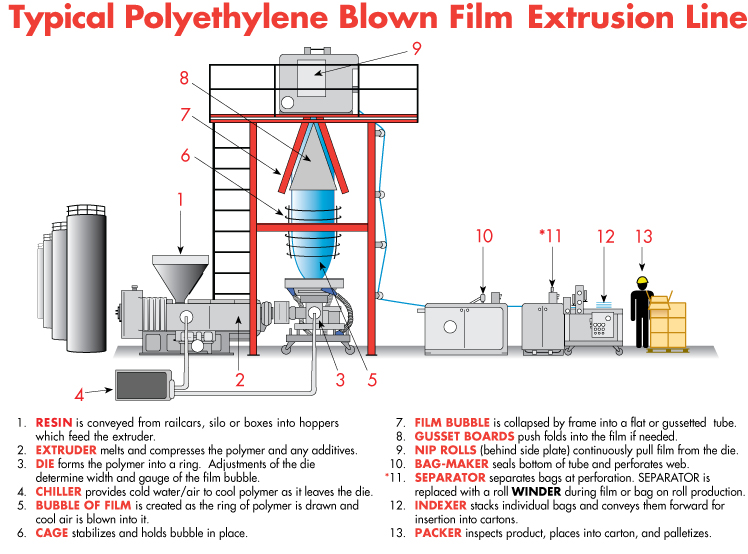
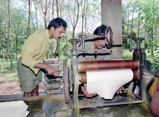
5. Production of Materials- (d) Plastics and Rubber: (i)Methods of production plastics; injection moulding, calendaring, etc (ii)Methods of producing rubber materials; natural and synthetic
6. Drawing Practice –(a) Isometric and Oblique Drawings: (i)Isometric drawing; definition and axes, Isometric drawing of simple shaped blocks without curves. (ii)Oblique drawing- definition, oblique drawing
7. Drawing Practice- (c) orthographic Projection and (d) One-point Perspective Drawing (c) Orthographic Projection:- (i) Principal planes- vertical and horizontal. (ii) Angles of projection- First angle and Third angle. (iii) Principal views- front, side, plan. (iv)Placing principal views in the quadrants. (v) Dimensioning techniques. (d) One- point Perspective Drawing: (i) definition (ii) principles (iii) practice.
8. Tools and Machines – (a) Woodwork Machines and (b) Simple woodwork Projects:(a) Woodwork: (i) Portable power tools; belt sander, hand drill, fret saw, etc. (ii) Machine; circular, hand saw, wood lathe, surface planer, thicknesser, sanders, drill, etc. (b) Simple woodwork Projects: (i) Common joints: butt, bridle, mortice and tenon. (ii) Classification: framing, widening, etc. (iii) Uses: tables, boxes, etc. (iv) Woodwork projects: boxes, photo frame. (v) Non-wood materials, adhesives, abrasives, hinges.
9. Tools and Processing- (a) Metalwork Machines: (i) Types of metalwork machines and their functions- cutting, turning, shaping, drilling, milling, grinding, etc. (ii) The centre lathe and its operation.
10. Tools and Processing- (b) Simple Metal work Projects: (i) Principles of measurement and measuring. (ii) Tools and cutting. (iii) Files and filing. (iv) Drills and drilling. (v) Bending and folding. (c) Soldering and Brazing: (i) Definition of soldering and brazing. (ii) Metal joining; soft soldering and hard soldering.
11. Revision.
Basic Textbooks
1. Basic Technology for Junior Secondary Schools or JS 3 (UBE Edition); By P.O Olawehinmi
2. NERDC Basic Technology for Junior Secondary Schools UBE Edition.
1ST TERM
WEEK 1
LESSON 1
TOPIC: CAREER PROSPECTS AND OPPORTUNITIES IN TECHNOLOGY.
CONTENT:
1. Technology related careers.
2. Employment prospects.
What is the Technology related career?
A career is a professional related job from which one earns his or her living in one’s adult life, which he/ she chooses and becomes engaged in it. The longer you stay in a particular career (job) the more competent and grounded you become in it.
Career Education is education which consists of those activities and experiences through which an individual learns of work.
Vocation is one’s primary work role at any given time.
Occupation is one’s primary work role in the world of paid employment.
Any career which involves the use of
I. Application of scientific principle
II. Conversion of material
III. Tools and machine are related to technology career, because they train students in the use of simple tools and therefore make the students to be useful in such professional jobs as installation and maintenance of parts of machine and structure etc. The course of study at the tertiary institution level, for the technology related careers are basically Engineering course.
These career courses include:
1. Agricultural Engineering
2. Aeronautical Engineering
3. Mechanical Engineering
4. Civil Engineering
5. Electrical Engineering
6. Computer Engineering
7. Chemical Engineering
8. Food Engineering
9. Mining Engineering
10. Metallurgical Engineering
1. Agricultural Engineering: This is the profession which focuses on the solution to the engineering problems of Agriculture. The agricultural engineering incorporates research and activities regarding the way farm wastes could be converted into more useful forms such as supply energy.
2. Aeronautical Engineering: This is the profession which concerned with the development, design, construction, uses and maintenance of aircraft of various kinds as well as the system which are used for their effective operation. Such aircrafts include airplane, helicopter, space shuttle, jet etc.
3. Mechanical Engineering: This is the profession which is concerned with the design, construction, operation and maintenance of machines and mechanical systems of various kinds. The major divisions of mechanical engineering are:
I. Production Engineering or Industrial Engineering: This is concerned with the development and application of various kinds of goods in industries.
II. Auto mobile Engineering is concerned mainly with vehicles of various kinds
III. Refrigeration Engineering is concerned with the development, application and maintenance of cooling and freezing system of both domestic and industrial levels.
4. Civil Engineering: This is the profession which is concerned with the design, construction, application, operation and maintenance of structure. The major divisions of civil Engineering are:
5. Building Engineering: This is concerned with building and structures for human habitation and activities involved in the production of shelter for other human interests.
6. High way Engineering: This concerns itself with the building of roads, land and water bridges as well as super high ways
7. Water resources Engineering: This is concerned with the design and construction of bore holes, canals, dams, Dredging works, and so forth.
8. Transportation Engineering: This is concerned with the integration of roads, rails and water transportation system for moving people and goods for the good of the society.
9. Electrical Engineering: The Electrical Engineering can be grouped into two broad areas:
I. Heavy current engineering: This is concerned with the design, construction, application and maintenance of transmitting, utilizing and distributing electricity for various uses. It also concerns itself with the application of electrical appliances such as transformer, electric motors, switches, generators, and conductors.
II. Electronics Engineering: This is concerned with the method through which electricity can be made for a more productive service and control the flow of electric current (electrons) in the internal circuit of Radio, Television DVD, and CD player and so forth. It also involves the development and application of telecommunication system, such as the design and construction of computers, calculator and so forth.
10. Computer Engineering: This is the profession which is concerned with the development, application and maintenance, installation of various forms of computer hard wares and the software. The hard ware aspect involves the development of computer accessories, integrated circuits (I.C)
11. Chemical Engineering: This is the profession which is concerned with the design, construction, installation, operation and maintenance of equipment and plant through which chemical substance can be handled and converted into useful forms. The related fields of chemical Engineering are:
I. Material Engineering: This is concerned with various useful materials such as paper, glass, silicon, plastic and so forth.
II. Nuclear Engineering: This is concerned with safe handling and the use of nuclear materials
III. Petrol Chemical Engineering: This is concerned with the maintenance, processing and uses of materials of petroleum origin.
12. Food Engineering: This is the profession which is concerned with the Development of food stuffs. It is concerned with industrial production of food and drinks on a large scale.
13. Mining Engineering: This is the profession which is concerned with the development of coal and other materials of fossil origin and precious stones.
14. Metallurgical Engineering: This is the profession which is concerned with ferrous and non-ferrous metals. It focuses on the way of finding the best methods for sourcing these materials as well as the best process for purifying them.

Employment Prospects.
Career Choice
The subject requirements for entry into these technology related career opportunities include;
1) English language
2) Mathematics
3) Physics
4) Chemistry
5) Biology
6) Geography
7) Technical Drawing.
To make a good career choice the following variables are necessary:
Subject combinations that is compulsory for your choice of career
Interest in the career and in the subjects related to the chosen career is necessary.
Knowledge of the work involved in the chosen career.
Academic achievement in the subjects required for the chosen career.
Difficulties perceived in the subjects required for the chosen career.
Motive for choosing the career.
Periods of Occupational choice.
1) Fantasy Period
2) Tentative Period
3) Realistic Period
EMPLOYMENT OPPORTUNITIES IN TECHNOLOGY
1. Employment in Industrial sector
2. Employment in Telecommunication sector
3. Employment in Educational sector
4. Employment in the service sector
5. Employment in Utilities
6. Employment in Consultancy sector
7. Employment in Construction sector
8. Employment in petroleum sector
9. Employment in farming and food processing sector.
EVALUATION:
I. What is a career?
II. Explain why it is necessary for someone to choose a career.
III. Mention eight job opportunities for technological engineers in a developing country like Nigeria.
ASSIGNMENT: Read New Basic Technology for Junior Secondary School, Bk 3, By P. O Olawehinmi. Pg 128 – 132 and answer the following questions:
a. State two areas where trees are found.
b. List five uses of wood at home.
c. Mention four stages a log of wood must pass through before it becomes workable and useful.
TOPIC: CAREER PROSPECTS AND OPPORTUNITIES IN TECHNOLOGY.
CONTENT:
1. Technology related careers.
2. Employment prospects.
What is the Technology related career?
A career is a professional related job from which one earns his or her living in one’s adult life, which he/ she chooses and becomes engaged in it. The longer you stay in a particular career (job) the more competent and grounded you become in it.
Career Education is education which consists of those activities and experiences through which an individual learns of work.
Vocation is one’s primary work role at any given time.
Occupation is one’s primary work role in the world of paid employment.
Any career which involves the use of
I. Application of scientific principle
II. Conversion of material
III. Tools and machine are related to technology career, because they train students in the use of simple tools and therefore make the students to be useful in such professional jobs as installation and maintenance of parts of machine and structure etc. The course of study at the tertiary institution level, for the technology related careers are basically Engineering course.
These career courses include:
1. Agricultural Engineering
2. Aeronautical Engineering
3. Mechanical Engineering
4. Civil Engineering
5. Electrical Engineering
6. Computer Engineering
7. Chemical Engineering
8. Food Engineering
9. Mining Engineering
10. Metallurgical Engineering
1. Agricultural Engineering: This is the profession which focuses on the solution to the engineering problems of Agriculture. The agricultural engineering incorporates research and activities regarding the way farm wastes could be converted into more useful forms such as supply energy.
2. Aeronautical Engineering: This is the profession which concerned with the development, design, construction, uses and maintenance of aircraft of various kinds as well as the system which are used for their effective operation. Such aircrafts include airplane, helicopter, space shuttle, jet etc.
3. Mechanical Engineering: This is the profession which is concerned with the design, construction, operation and maintenance of machines and mechanical systems of various kinds. The major divisions of mechanical engineering are:
I. Production Engineering or Industrial Engineering: This is concerned with the development and application of various kinds of goods in industries.
II. Auto mobile Engineering is concerned mainly with vehicles of various kinds
III. Refrigeration Engineering is concerned with the development, application and maintenance of cooling and freezing system of both domestic and industrial levels.
4. Civil Engineering: This is the profession which is concerned with the design, construction, application, operation and maintenance of structure. The major divisions of civil Engineering are:
5. Building Engineering: This is concerned with building and structures for human habitation and activities involved in the production of shelter for other human interests.
6. High way Engineering: This concerns itself with the building of roads, land and water bridges as well as super high ways
7. Water resources Engineering: This is concerned with the design and construction of bore holes, canals, dams, Dredging works, and so forth.
8. Transportation Engineering: This is concerned with the integration of roads, rails and water transportation system for moving people and goods for the good of the society.
9. Electrical Engineering: The Electrical Engineering can be grouped into two broad areas:
I. Heavy current engineering: This is concerned with the design, construction, application and maintenance of transmitting, utilizing and distributing electricity for various uses. It also concerns itself with the application of electrical appliances such as transformer, electric motors, switches, generators, and conductors.
II. Electronics Engineering: This is concerned with the method through which electricity can be made for a more productive service and control the flow of electric current (electrons) in the internal circuit of Radio, Television DVD, and CD player and so forth. It also involves the development and application of telecommunication system, such as the design and construction of computers, calculator and so forth.
10. Computer Engineering: This is the profession which is concerned with the development, application and maintenance, installation of various forms of computer hard wares and the software. The hard ware aspect involves the development of computer accessories, integrated circuits (I.C)
11. Chemical Engineering: This is the profession which is concerned with the design, construction, installation, operation and maintenance of equipment and plant through which chemical substance can be handled and converted into useful forms. The related fields of chemical Engineering are:
I. Material Engineering: This is concerned with various useful materials such as paper, glass, silicon, plastic and so forth.
II. Nuclear Engineering: This is concerned with safe handling and the use of nuclear materials
III. Petrol Chemical Engineering: This is concerned with the maintenance, processing and uses of materials of petroleum origin.
12. Food Engineering: This is the profession which is concerned with the Development of food stuffs. It is concerned with industrial production of food and drinks on a large scale.
13. Mining Engineering: This is the profession which is concerned with the development of coal and other materials of fossil origin and precious stones.
14. Metallurgical Engineering: This is the profession which is concerned with ferrous and non-ferrous metals. It focuses on the way of finding the best methods for sourcing these materials as well as the best process for purifying them.
Employment Prospects.
Career Choice
The subject requirements for entry into these technology related career opportunities include;
1) English language
2) Mathematics
3) Physics
4) Chemistry
5) Biology
6) Geography
7) Technical Drawing.
To make a good career choice the following variables are necessary:
Subject combinations that is compulsory for your choice of career
Interest in the career and in the subjects related to the chosen career is necessary.
Knowledge of the work involved in the chosen career.
Academic achievement in the subjects required for the chosen career.
Difficulties perceived in the subjects required for the chosen career.
Motive for choosing the career.
Periods of Occupational choice.
1) Fantasy Period
2) Tentative Period
3) Realistic Period
EMPLOYMENT OPPORTUNITIES IN TECHNOLOGY
1. Employment in Industrial sector
2. Employment in Telecommunication sector
3. Employment in Educational sector
4. Employment in the service sector
5. Employment in Utilities
6. Employment in Consultancy sector
7. Employment in Construction sector
8. Employment in petroleum sector
9. Employment in farming and food processing sector.
EVALUATION:
I. What is a career?
II. Explain why it is necessary for someone to choose a career.
III. Mention eight job opportunities for technological engineers in a developing country like Nigeria.
ASSIGNMENT: Read New Basic Technology for Junior Secondary School, Bk 3, By P. O Olawehinmi. Pg 128 – 132 and answer the following questions:
a. State two areas where trees are found.
b. List five uses of wood at home.
c. Mention four stages a log of wood must pass through before it becomes workable and useful.
WEEK 2
LESSON 2
TOPIC : PRODUCTION OF MATERIALS.
CONTENT:
1. Production of Wood Materials, Timber Growth and Felling.
2.Properties of good timber preservatives.
3. Common timber defects, twist, bowing, cupping, etc
4. Methods of cutting veneers
5. Types and manufacture of laminated boards
Production of Wood Materials, Timber Growth and Felling.
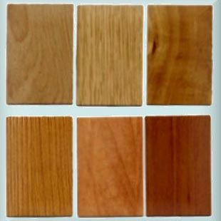
Wood is one of the oldest materials in technology. It is composed of cellulose, lignin and other minor materials such as starch, resins, wax and gum. When closely observed, wood is seen to be made up of tiny thread-like units called fibres.
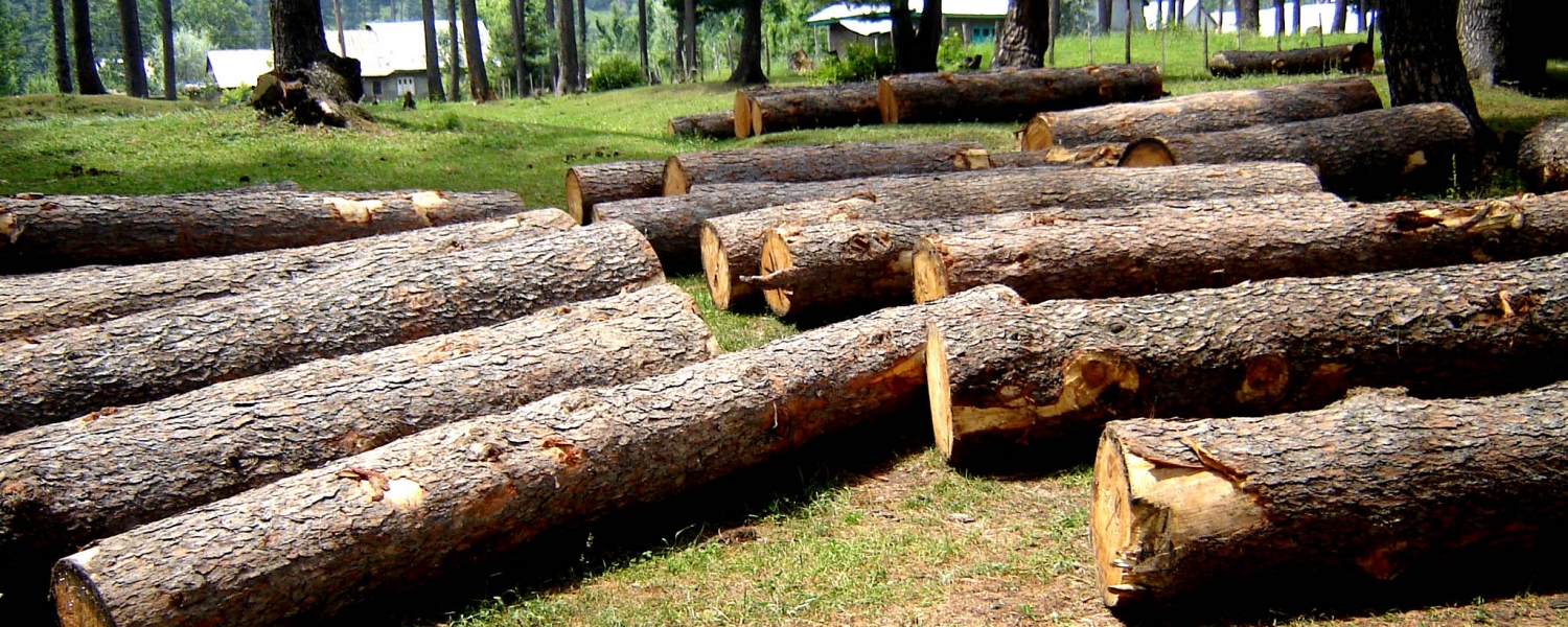
Wood is classified as either hardwood or softwood. The older the tree, the bigger it becomes. When the trees become mature, it is felled by the use of axe or chain saw and sliced into standard market sizes for different purpose in furniture making and construction of buildings.
Hard Wood: These are got from deciduous tree. They have broad leaves and their seeds are enclosed in cases. Some examples include Mahogany, Afara, Opepe, Abura, Omo, Agba, Sapele, Oak, Jarrah and Teak.
Soft Wood : These are got from coniferous trees (i.e. trees that bear naked seeds which are in cones). They have narrow leaves and grow in the temperate regions of the world. Examples include cedar, pine, fir, larch, spruce and European whitewood.
Tree Growth: Trees undergo two types of growth:
1. Primary or vertical growth. This takes place mainly near the tips of the root and shoots of the tree and continues for the most part of the plant’s life.
2. Secondary or horizontal growth. This results in increase in girth and takes place mostly in the cambium.
The stages of processing wood before becoming useful are:
i. Felling
ii. Conversion
iii. Seasoning
iv. Preservation.
TYPES OF TREE:
Deciduous Tree = Hard wood
Coniferous Tree = Soft wood
THE MAIN PARTS OF A TREE.
1) The Roots
2) The Stem / Trunk
3) The branches
4) The bark
5) The Leaves
The felling of trees for timber use is done broadly in two areas in Nigeria.
I. The Free Area
II. The Forest Reserve Area.
1. The Free Area: This is the area outside the forest reserve area and it is owned by individuals. The amount of money paid to the government by the timber contractor for permission to cut down any tree in the Free Area for commercial purposes is called Tariff.
2. The Forest Reserve Area: This is the government owned area. The forest reserved area is guarded by the forest guards. Hence, it is difficult for anybody to cut down any tree in the forest reserve area without the permission from the government. The amount of money paid for the timber to be cut down in the forest reserve area depends on the volume of the trees to be cut down. Hence, this is termed O.T.V i.e Out Turn Volume.
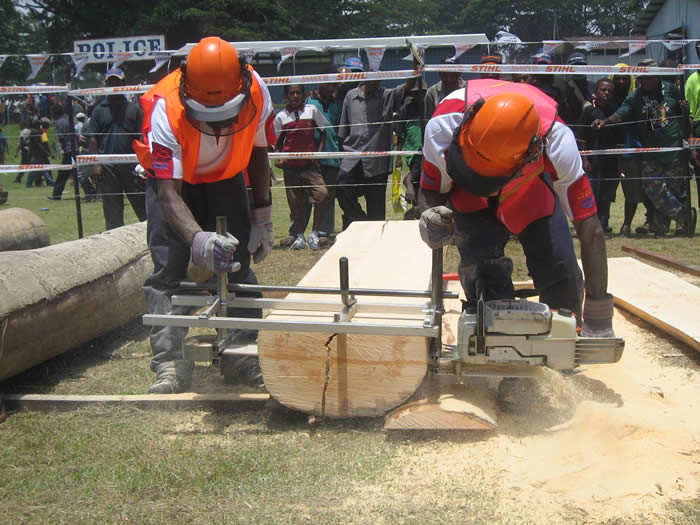
The portable powered saw used in cutting down trees is called Chain saw.
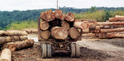
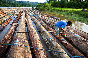
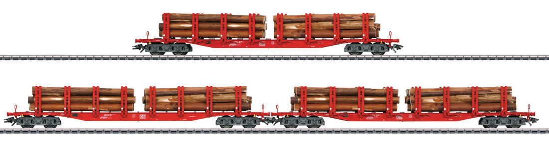
METHODS OF TRANSPORTING LOGS.
Logs are transported from the forest to sawmill, where they are sawn into the required lengths and sizes of planks. Methods of transporting logs are:
I. By Road Transport
II. By Train
III. By Waterways.
CONVERSION OF WOOD.
The conversion of wood is the process of sawing logs of timber with wood working machines (Sawing machine) in the Sawmills into planks of required size or marketable size or commercial sizes. The popular methods of conversion of logs of timber into planks are:
I. The plain (through and through) method
II. The quarter sawn method
III. The tangential sawn method
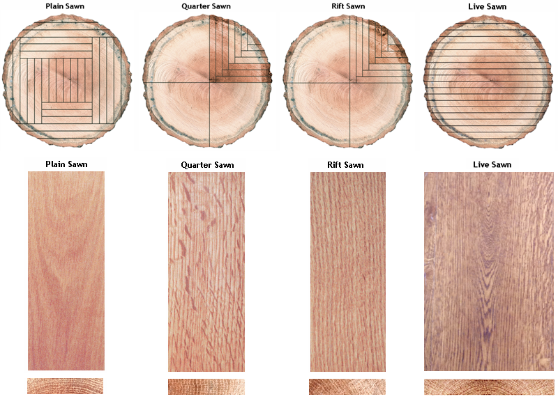
1. Plain Sawn Method: The plain sawn method is also known as through and through method. In plain sawn method, planks are sawn parallel to the axis of the tree trunk. This method of sawing planks is used for producing planks which are needed for doors, windows and roofs of houses. The planks are cut parallel to the axis of the wood.
2. Quarter Sawn Method: This method is simply the sawing of timber plank after plank. The Quarter sawn method is the method of conversion of timber along the rays of the wood. In quarter sawn method, planks are cut at right angles to the growth rings. This method of sawing planks is used for producing planks which are cut with the growth rings running through the thickness of the planks.

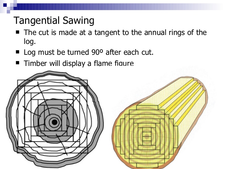
3. Tangential Sawn Method: Tangential sawn method of sawing planks in which the planks are cut so that their wide edges are tangential to the growth rings.
Some of the machines used for conversion of trees are:
a) The circular saw
b) The horizontal log band saw
c) The vertical log band saw
d) The frame saw.
SEASONING OF WOOD.
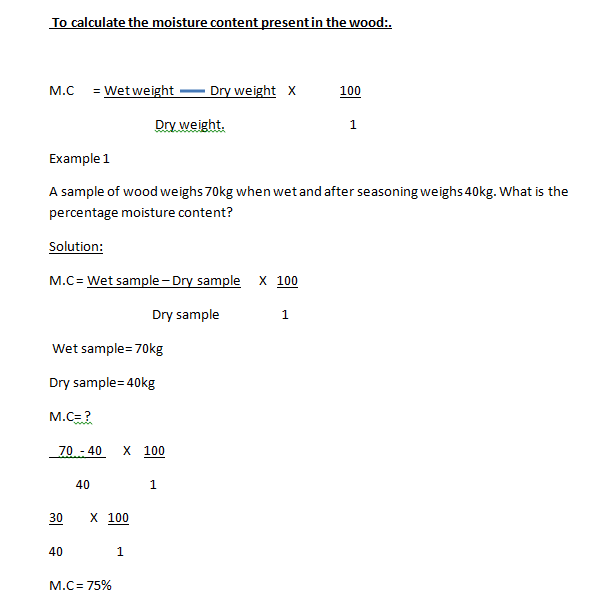
Wood contains a great deal of water. The water content must be reduced by a process known as seasoning before the wood can become useful. Seasoning of wood is the process of drying or reducing the excess water in the wood. The excess water is called moisture content.
Methods of seasoning wood:
There are two methods of seasoning wood.
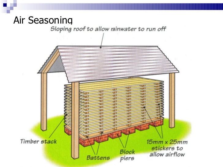
1. The Air seasoning( Natural Seasoning)
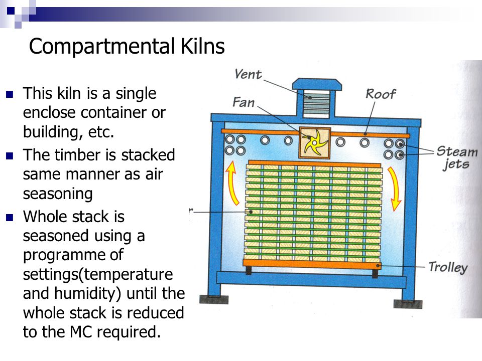
2. The Kiln Seasoning ( Artificial Seasoning)
1. The Air Seasoning: This is also called Natural seasoning. This method of seasoning wood involves stacking the wood in the open shed for a long period of time and allows it to dry naturally. The stacked planks (wood) are arranged on top of one another with pieces of small wood called stackers in between them in order to allow the free circulation of air.
Advantages:
It is relatively cheap.
It requires little attention
Disadvantages:
The rate of drying is slow, so it takes a very long time to be seasoned.
There is no control over the drying process.
2. The Kiln Seasoning: This method of seasoning wood, involves stacking the timber in a specially heated chamber. The planks are stacked in the same way as in the air seasoning, but the planks are placed in a specially heated chamber called kiln. In this process, the rate of drying planks is faster than air seasoning method.
REASONS FOR SEASONING WOOD
1. It makes the wood become lighter in weight.
2. It makes the wood become more stable.
3. It makes the wood to take paints, polishes and preservatives easily.
4. It makes the wood to be durable i.e. last longer
5. It reduces the attack of fungi and insects on wood.
6. It reduces the moisture content of the wood.
To calculate the moisture content present in the wood:.
Class work.
1. The weight of sample of wood before drying was found to be 120kg. The percentage moisture content was found to be 50%, what is the weight of the sample of the wood after drying?
Answer= 80kg.
2. The weight of a sample of wood after drying was found to be 60kg. The percentage moisture content was 40%, what is the weight of the wood before drying?
Answer= 84kg.
LESSON 3
Common Timber Defects
Defects in timber
A defect in timber is any feature in timber that reduces the quality and the market value of the timber.
Types of defects in timber.
Defects in timber can be grouped into two types:
I. The Natural defects
II. The Artificial defects.
THE NATURAL DEFECTS:
The Natural defects in timber are those defects that are caused by natural occurrences such as thunder, rain, growth circumstances etc. Examples of natural defects are:
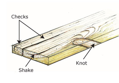
Shakes : These are disruptions in the wood fibre which show up as splits and separation of parts of the stem of a tree.
Examples:
Heart shakes: This is visible on the cross-section of the centre of the log, extending along the rays
Star Shakes: This is similar to the heart shake, but with more spilts like star.
Cup Shakes: These are visible cracks which go round the growth ring of the wood.
Ring Shakes: These are circular cracks on the timber.
Knot: knots are caused by branches.
https://www.slideshare.net/RajatYadav18 ... nd-defects
THE ARTIFICIAL DEFECTS:
The artificial defects are those defects that are caused by human beings through careless handling of the wood while processing.
Examples :
Cup: This is the concave curvature across the face of the timber.
Bow: This is either concave or convex curvature along the length of the plank.
Check: This is the separation of the wood along the grains of the wood.
Twist: This is the spiral form of distortion along the length of the plank.
Insect Attack: This is the visible minute holes seen on the surface of the wood. The insects always attack sap wood.
Warps: The warp in timber is called twists. They are caused by improper seasoning procedures of wood fibers.
https://www.slideshare.net/MrWoodwork/13-diseases
Wood preservation.
This is the process of prolonging the life span of wood by the application of wood preservatives.
Wood preservatives are applied to the planks to prevent insect and fungal attack.
Wood Preservatives: These are the chemicals used to poison the destructive agents in the wood. E.g. fungi, insects, and termites. Some of the chemicals used as the wood preservatives are solignum, creosote, phenols, paints etc.
Types of wood preservatives: There are three major types of wood preservatives depending on the method of mixing.
1. Water soluble preservatives: These are the chemicals that can be mixed thoroughly with water only.
2. Oils soluble preservatives: These are the chemicals that can be mixed thoroughly with oils only.
3. Solvent soluble preservatives: These are the chemicals that can be mixed thoroughly with evaporating liquids only.
Methods of Applying the Preservatives:
The methods of applying good preservatives to dry wood are:
i. Brushing Method: This is the process of using brush to apply preservatives to the wood.
ii. Spraying Method: This is the process of using spraying gun to apply preservatives to the wood.
iii. Cold Immersion Method: This is the method of immersing (dipping) planks in an unheated solution of preservatives for one or two days.
iv. Open Tank Method (Hot and Cold Method): This is the process in which the plank is immersed in a tank containing hot liquid preservatives. This process is normally used for Treating poles and fence posts.
v. Pressure Treatment Method: This is process in which planks are placed inside an enclosed metal cylinder. In the process, the preservatives are being forced into the plank under high pressure. This enables the wood to be preserved either by pumping the solution into the entire cell cavity or by merely coating the cell wall with the preservatives and finally draining the cell cavity, leaving the cell saturated with preservatives, when the process is completed.
Properties of Good preservatives:
The following are the properties of good preservatives:
I. It must be poisonous to the destructive agents.
II. It must be safe to handle
III. It must be permanent to the wood on application
IV. It must be easy to apply on the wood
V. It must be chemically stable for a long time on application to the wood.
LESSON 4
Veneer
Veneers : A veneer is a thin layer of sliced sheet obtained from wood. The thickness of the veneers ranges from 0.5mm – 3.0mm
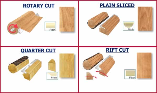
Method of making veneers
1. Rotary method
2. Slicing method
3. Eccentric method
1. Rotary Method. The rotary method requires the wood to be steamed in other to loosen the fiber and make it easy to peel with knives attached to the lathe machine. With the lathe machine, large sheets of veneers can be produced and cut to marked sizes for commercial purposes.
2. Slicing Method. The timber is safely attached to the slicing machine. The knife or the cutting blade on the machine will be set on the wood depending on the thickness of the veneer required. The thickness is set after every stroke. On switching on the machine, it slices the sheet of wood to the required thickness depending on the purpose of the veneer.
3. Eccentric Peeling. In eccentric peeling method the log of wood is first cut into four parts each of which is called quarter log. Each log is placed on the lathe machine with the sapwood at the centre. The peeling of the veneer commences from the heartwood to the sapwood.
Types and Manufacture of Laminated Boards.
Laminated boards are man-made boards manufactured by man from veneers, wood waste, synthetic and impregnated paper bonds. Types and methods of manufacture of laminated boards are as follows;
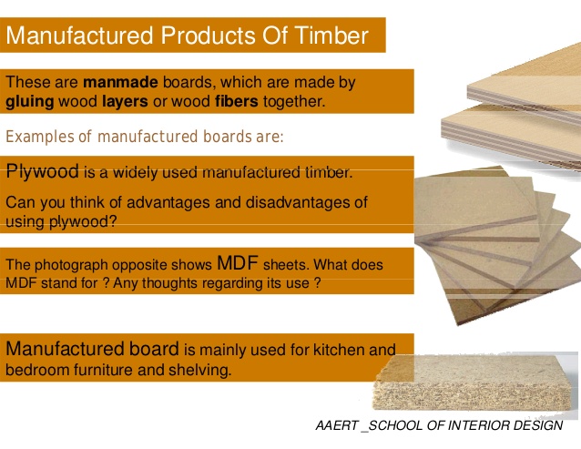
1. Examples of Man-made boards.
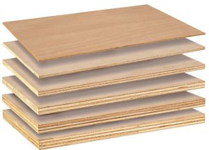
I. Plywood
II. Particle board
III. Laminated board
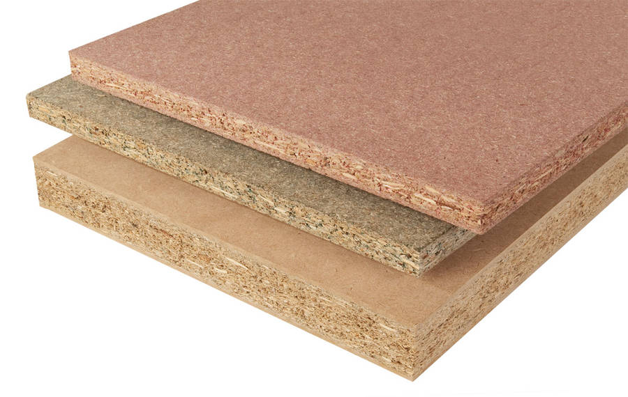
IV. Chip board
V. Composite board
VI. Pattern board
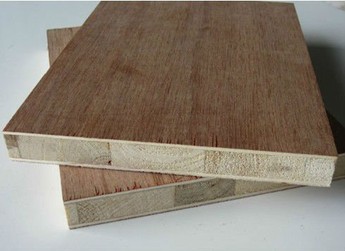
VII. Block boards
1. Ply wood
Plywood is produced by bonding three or more veneers together with strong glue. The grain of each sheet of veneer is laid at right angle to each other. After successfully bonding the sheets of veneers together, they are cut in different sizes for commercial purposes such as 2440mm X 1220mm with thickness, ranging from 1 to 25mm.
2. Chipboards. Chipboards are produced with wood chips. The chips which are wastes from wood are mixed with glue. After mixing thoroughly with glue they are pressed together and heated to form boards. The boards can be veneered to form smooth surfaces. Chipboards can be used in the construction of kitchen cabinets.
3. Blockboards. Blockboards are made of strips of wood placed side by side and covered with veneers. It is similar to plywood. But it is thicker, stronger and cannot be bent easily. They can be used in the construction of different types of cabinets including tables, cupboards and room dividers.
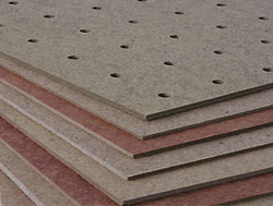
4. Hardboards :They are manufactured from waste wood mixed and mashed with hardeners and bonding materials like glue. After mixing with glue or any other bonding material they are pressed with great pressure and high temperature. Hardboards can be faced with veneer, enamel and plastics.
5. Laminated Plastics: They are manufactured from synthetic resin and impregnated paper. The materials are bonded together with great pressure and heat is applied. Laminated plastics do not allow the passage of water through them. They are strong and durable.
ADVANTAGES OF MANUFACTURED BOARDS.
Manufactured boards have the following advantages over solid wood.
i. They are available in flat large sheets.
ii. They can be cut easily and worked on.
iii. They can be easily nailed without splitting.
iv. They can be bent to form curves.
v. They do not check or warp like solid wood.
EVALUATION:
1) What is conversion of timber?
2) Mention three methods of conversion of timber.
3) Define seasoning.
4) Give three advantages of seasoning.
5) Mention five defects in timber.
6) List five properties of good wood preservatives.
ASSIGNMENT:
1. Draw a growing tree and label its parts.
2. State the function of each part labeled in (1) above.
3. Give three advantages of manufactured boards over solid wood.
4. Read your textbook ‘ Basic Technology for Junior Secondary School’, By P.O Olawehinmi. Pgs 134-136 Study the topic ‘Production of Metallic Materials’ against the next lesson.
TOPIC : PRODUCTION OF MATERIALS.
CONTENT:
1. Production of Wood Materials, Timber Growth and Felling.
2.Properties of good timber preservatives.
3. Common timber defects, twist, bowing, cupping, etc
4. Methods of cutting veneers
5. Types and manufacture of laminated boards
Production of Wood Materials, Timber Growth and Felling.
Wood is one of the oldest materials in technology. It is composed of cellulose, lignin and other minor materials such as starch, resins, wax and gum. When closely observed, wood is seen to be made up of tiny thread-like units called fibres.
Wood is classified as either hardwood or softwood. The older the tree, the bigger it becomes. When the trees become mature, it is felled by the use of axe or chain saw and sliced into standard market sizes for different purpose in furniture making and construction of buildings.
Hard Wood: These are got from deciduous tree. They have broad leaves and their seeds are enclosed in cases. Some examples include Mahogany, Afara, Opepe, Abura, Omo, Agba, Sapele, Oak, Jarrah and Teak.
Soft Wood : These are got from coniferous trees (i.e. trees that bear naked seeds which are in cones). They have narrow leaves and grow in the temperate regions of the world. Examples include cedar, pine, fir, larch, spruce and European whitewood.
Tree Growth: Trees undergo two types of growth:
1. Primary or vertical growth. This takes place mainly near the tips of the root and shoots of the tree and continues for the most part of the plant’s life.
2. Secondary or horizontal growth. This results in increase in girth and takes place mostly in the cambium.
The stages of processing wood before becoming useful are:
i. Felling
ii. Conversion
iii. Seasoning
iv. Preservation.
TYPES OF TREE:
Deciduous Tree = Hard wood
Coniferous Tree = Soft wood
THE MAIN PARTS OF A TREE.
1) The Roots
2) The Stem / Trunk
3) The branches
4) The bark
5) The Leaves
The felling of trees for timber use is done broadly in two areas in Nigeria.
I. The Free Area
II. The Forest Reserve Area.
1. The Free Area: This is the area outside the forest reserve area and it is owned by individuals. The amount of money paid to the government by the timber contractor for permission to cut down any tree in the Free Area for commercial purposes is called Tariff.
2. The Forest Reserve Area: This is the government owned area. The forest reserved area is guarded by the forest guards. Hence, it is difficult for anybody to cut down any tree in the forest reserve area without the permission from the government. The amount of money paid for the timber to be cut down in the forest reserve area depends on the volume of the trees to be cut down. Hence, this is termed O.T.V i.e Out Turn Volume.
The portable powered saw used in cutting down trees is called Chain saw.
METHODS OF TRANSPORTING LOGS.
Logs are transported from the forest to sawmill, where they are sawn into the required lengths and sizes of planks. Methods of transporting logs are:
I. By Road Transport
II. By Train
III. By Waterways.
CONVERSION OF WOOD.
The conversion of wood is the process of sawing logs of timber with wood working machines (Sawing machine) in the Sawmills into planks of required size or marketable size or commercial sizes. The popular methods of conversion of logs of timber into planks are:
I. The plain (through and through) method
II. The quarter sawn method
III. The tangential sawn method
1. Plain Sawn Method: The plain sawn method is also known as through and through method. In plain sawn method, planks are sawn parallel to the axis of the tree trunk. This method of sawing planks is used for producing planks which are needed for doors, windows and roofs of houses. The planks are cut parallel to the axis of the wood.
2. Quarter Sawn Method: This method is simply the sawing of timber plank after plank. The Quarter sawn method is the method of conversion of timber along the rays of the wood. In quarter sawn method, planks are cut at right angles to the growth rings. This method of sawing planks is used for producing planks which are cut with the growth rings running through the thickness of the planks.
3. Tangential Sawn Method: Tangential sawn method of sawing planks in which the planks are cut so that their wide edges are tangential to the growth rings.
Some of the machines used for conversion of trees are:
a) The circular saw
b) The horizontal log band saw
c) The vertical log band saw
d) The frame saw.
SEASONING OF WOOD.
Wood contains a great deal of water. The water content must be reduced by a process known as seasoning before the wood can become useful. Seasoning of wood is the process of drying or reducing the excess water in the wood. The excess water is called moisture content.
Methods of seasoning wood:
There are two methods of seasoning wood.
1. The Air seasoning( Natural Seasoning)
2. The Kiln Seasoning ( Artificial Seasoning)
1. The Air Seasoning: This is also called Natural seasoning. This method of seasoning wood involves stacking the wood in the open shed for a long period of time and allows it to dry naturally. The stacked planks (wood) are arranged on top of one another with pieces of small wood called stackers in between them in order to allow the free circulation of air.
Advantages:
It is relatively cheap.
It requires little attention
Disadvantages:
The rate of drying is slow, so it takes a very long time to be seasoned.
There is no control over the drying process.
2. The Kiln Seasoning: This method of seasoning wood, involves stacking the timber in a specially heated chamber. The planks are stacked in the same way as in the air seasoning, but the planks are placed in a specially heated chamber called kiln. In this process, the rate of drying planks is faster than air seasoning method.
REASONS FOR SEASONING WOOD
1. It makes the wood become lighter in weight.
2. It makes the wood become more stable.
3. It makes the wood to take paints, polishes and preservatives easily.
4. It makes the wood to be durable i.e. last longer
5. It reduces the attack of fungi and insects on wood.
6. It reduces the moisture content of the wood.
To calculate the moisture content present in the wood:.
Class work.
1. The weight of sample of wood before drying was found to be 120kg. The percentage moisture content was found to be 50%, what is the weight of the sample of the wood after drying?
Answer= 80kg.
2. The weight of a sample of wood after drying was found to be 60kg. The percentage moisture content was 40%, what is the weight of the wood before drying?
Answer= 84kg.
LESSON 3
Common Timber Defects
Defects in timber
A defect in timber is any feature in timber that reduces the quality and the market value of the timber.
Types of defects in timber.
Defects in timber can be grouped into two types:
I. The Natural defects
II. The Artificial defects.
THE NATURAL DEFECTS:
The Natural defects in timber are those defects that are caused by natural occurrences such as thunder, rain, growth circumstances etc. Examples of natural defects are:
Shakes : These are disruptions in the wood fibre which show up as splits and separation of parts of the stem of a tree.
Examples:
Heart shakes: This is visible on the cross-section of the centre of the log, extending along the rays
Star Shakes: This is similar to the heart shake, but with more spilts like star.
Cup Shakes: These are visible cracks which go round the growth ring of the wood.
Ring Shakes: These are circular cracks on the timber.
Knot: knots are caused by branches.
https://www.slideshare.net/RajatYadav18 ... nd-defects
THE ARTIFICIAL DEFECTS:
The artificial defects are those defects that are caused by human beings through careless handling of the wood while processing.
Examples :
Cup: This is the concave curvature across the face of the timber.
Bow: This is either concave or convex curvature along the length of the plank.
Check: This is the separation of the wood along the grains of the wood.
Twist: This is the spiral form of distortion along the length of the plank.
Insect Attack: This is the visible minute holes seen on the surface of the wood. The insects always attack sap wood.
Warps: The warp in timber is called twists. They are caused by improper seasoning procedures of wood fibers.
https://www.slideshare.net/MrWoodwork/13-diseases
Wood preservation.
This is the process of prolonging the life span of wood by the application of wood preservatives.
Wood preservatives are applied to the planks to prevent insect and fungal attack.
Wood Preservatives: These are the chemicals used to poison the destructive agents in the wood. E.g. fungi, insects, and termites. Some of the chemicals used as the wood preservatives are solignum, creosote, phenols, paints etc.
Types of wood preservatives: There are three major types of wood preservatives depending on the method of mixing.
1. Water soluble preservatives: These are the chemicals that can be mixed thoroughly with water only.
2. Oils soluble preservatives: These are the chemicals that can be mixed thoroughly with oils only.
3. Solvent soluble preservatives: These are the chemicals that can be mixed thoroughly with evaporating liquids only.
Methods of Applying the Preservatives:
The methods of applying good preservatives to dry wood are:
i. Brushing Method: This is the process of using brush to apply preservatives to the wood.
ii. Spraying Method: This is the process of using spraying gun to apply preservatives to the wood.
iii. Cold Immersion Method: This is the method of immersing (dipping) planks in an unheated solution of preservatives for one or two days.
iv. Open Tank Method (Hot and Cold Method): This is the process in which the plank is immersed in a tank containing hot liquid preservatives. This process is normally used for Treating poles and fence posts.
v. Pressure Treatment Method: This is process in which planks are placed inside an enclosed metal cylinder. In the process, the preservatives are being forced into the plank under high pressure. This enables the wood to be preserved either by pumping the solution into the entire cell cavity or by merely coating the cell wall with the preservatives and finally draining the cell cavity, leaving the cell saturated with preservatives, when the process is completed.
Properties of Good preservatives:
The following are the properties of good preservatives:
I. It must be poisonous to the destructive agents.
II. It must be safe to handle
III. It must be permanent to the wood on application
IV. It must be easy to apply on the wood
V. It must be chemically stable for a long time on application to the wood.
LESSON 4
Veneer
Veneers : A veneer is a thin layer of sliced sheet obtained from wood. The thickness of the veneers ranges from 0.5mm – 3.0mm
Method of making veneers
1. Rotary method
2. Slicing method
3. Eccentric method
1. Rotary Method. The rotary method requires the wood to be steamed in other to loosen the fiber and make it easy to peel with knives attached to the lathe machine. With the lathe machine, large sheets of veneers can be produced and cut to marked sizes for commercial purposes.
2. Slicing Method. The timber is safely attached to the slicing machine. The knife or the cutting blade on the machine will be set on the wood depending on the thickness of the veneer required. The thickness is set after every stroke. On switching on the machine, it slices the sheet of wood to the required thickness depending on the purpose of the veneer.
3. Eccentric Peeling. In eccentric peeling method the log of wood is first cut into four parts each of which is called quarter log. Each log is placed on the lathe machine with the sapwood at the centre. The peeling of the veneer commences from the heartwood to the sapwood.
Types and Manufacture of Laminated Boards.
Laminated boards are man-made boards manufactured by man from veneers, wood waste, synthetic and impregnated paper bonds. Types and methods of manufacture of laminated boards are as follows;
1. Examples of Man-made boards.
I. Plywood
II. Particle board
III. Laminated board
IV. Chip board
V. Composite board
VI. Pattern board
VII. Block boards
1. Ply wood
Plywood is produced by bonding three or more veneers together with strong glue. The grain of each sheet of veneer is laid at right angle to each other. After successfully bonding the sheets of veneers together, they are cut in different sizes for commercial purposes such as 2440mm X 1220mm with thickness, ranging from 1 to 25mm.
2. Chipboards. Chipboards are produced with wood chips. The chips which are wastes from wood are mixed with glue. After mixing thoroughly with glue they are pressed together and heated to form boards. The boards can be veneered to form smooth surfaces. Chipboards can be used in the construction of kitchen cabinets.
3. Blockboards. Blockboards are made of strips of wood placed side by side and covered with veneers. It is similar to plywood. But it is thicker, stronger and cannot be bent easily. They can be used in the construction of different types of cabinets including tables, cupboards and room dividers.
4. Hardboards :They are manufactured from waste wood mixed and mashed with hardeners and bonding materials like glue. After mixing with glue or any other bonding material they are pressed with great pressure and high temperature. Hardboards can be faced with veneer, enamel and plastics.
5. Laminated Plastics: They are manufactured from synthetic resin and impregnated paper. The materials are bonded together with great pressure and heat is applied. Laminated plastics do not allow the passage of water through them. They are strong and durable.
ADVANTAGES OF MANUFACTURED BOARDS.
Manufactured boards have the following advantages over solid wood.
i. They are available in flat large sheets.
ii. They can be cut easily and worked on.
iii. They can be easily nailed without splitting.
iv. They can be bent to form curves.
v. They do not check or warp like solid wood.
EVALUATION:
1) What is conversion of timber?
2) Mention three methods of conversion of timber.
3) Define seasoning.
4) Give three advantages of seasoning.
5) Mention five defects in timber.
6) List five properties of good wood preservatives.
ASSIGNMENT:
1. Draw a growing tree and label its parts.
2. State the function of each part labeled in (1) above.
3. Give three advantages of manufactured boards over solid wood.
4. Read your textbook ‘ Basic Technology for Junior Secondary School’, By P.O Olawehinmi. Pgs 134-136 Study the topic ‘Production of Metallic Materials’ against the next lesson.
WEEK 3
LESSON 5
TOPIC: PRODUCTION OF METALLIC MATERIALS.
CONTENT :
1. Production of metals: smelting, casting, etc
2. Carbon properties of steels.
3. Metal Alloys
4. Clay, ceramics and glass.
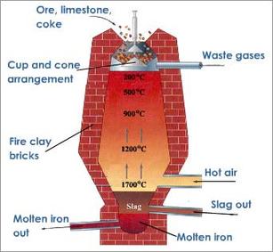
Metallic materials are materials which are referred to as good conductors of heat and electricity. Metals are gotten from Iron ore which is the raw material for metal production. The Iron Ore is dug from the ground along with the impurities (coke, hot air, limestone with Iron Ore).
When the Iron Ore is dug up from the ground, it cannot be used as it contains some impurities, it undergoes certain processes during which these impurities are removed and other substances are added. Since these impurities cannot be removed from iron-ore in its solid state, it is converted into a liquid state by heating. Thus process is known as smelting. The equipment used for this process is called a furnace. After removing these impurities from Iron Ore, the product left is called Pig-Iron.The Pig iron in its ordinary state cannot be used without further processing; this is because pig iron contains saturated iron and carbon. This is weak and can break easily. Hence, it forms the basis of all ferrous metals containing about 45% carbon. In order to render pig iron usable such as cast Iron, steels and wrought Iron, the amount of carbon it contains must be reduced.
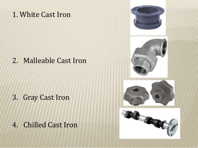
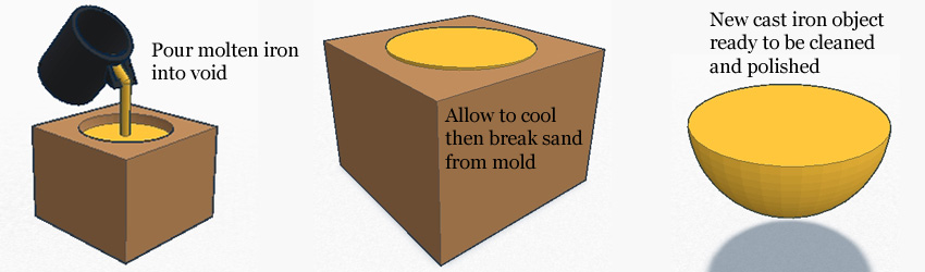
1. Cast Iron: This is obtained when pig Iron is put into a cupola furnace. In this furnace, the carbon content is reduced to about 3.5%. The molten Iron is then poured from the furnace into a container, called mould, so as to solidify it. This process of pouring molten iron into a mould to solidify into a described shape is called casting, hence, the name cast iron.
Examples of cast iron
i. Ductile (chilled) cast iron
ii. Malleable cast iron
iii. Grey cast iron
iv. White cast iron.
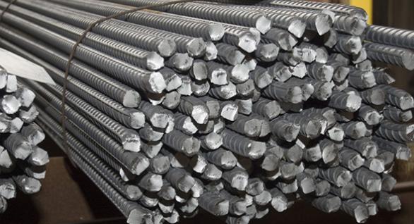
2. Steel: This is obtained when the carbon content of pig iron is reduced to 1.5 or less. Steels are named according to the carbon content present in them. These steels are called Plain Carbon Steels because they are made up of carbon and iron.
I. Low carbon steel: (mild steel) this contains about 0.3% or less of carbon.
II. Medium carbon steel: This contain between 0.3%- 0.5% of carbon.
III. High carbon steel: This contains between 0.6%- 1.5% of carbon.
Furnaces used are open hearth and Bessemer converter.
3. Wrought Iron: The wrought iron is obtained by removing the carbon content present in the pig iron. It is soft, easily bent and does not break or rust easily. This is almost pure iron with little slag on it. The wrought iron has no carbon content in them. It is almost rust proof. It is malleable and ductile and can be easily forged into the required shape. Wrought Iron is used in the manufacture of chairs, boilers, plates, gears and so forth.
Casting: This is the process of melting and pouring molten metal into the mould where it cools down to solidify.
Smelting: This is the process of extracting metals from its iron-ore to a liquid state by heating. In this process, all impurities are extracted from the Iron- Ore to form pig-iron.
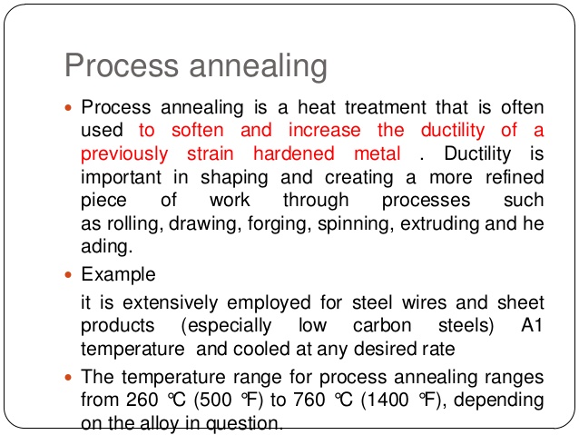
Annealing: This is the process by which metals can be softened.
Alloy steels
All steels are alloys because they contain both iron and carbon. Alloy steel is a combination of plain carbon steel and one or more other elements which are placed in the electric furnace and then heated. This molten mixture is then poured into a mould container and then cooled to solidify. The alloy steels are:
I. High tensile steels: This is also known as Nickel - chrome alloys. These contain iron, carbon, nickel and chromium. They are used for making machine parts which require high tensility and strength.
II. High Speed steels: These contain iron, carbon, tungsten and chromium. Other forms of high speed steels contain cobalt and vanadium. They are used as cutting edges in machines where friction causes excessive heat due to continuous cutting.
III. Stainless steels: These contain Iron, carbon, Nickel or chromium. Nickel and chromium are principally used as coating for the metals so as to make it resistant to corrosion. They are produced in electric furnace.
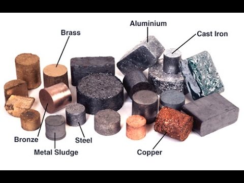
PROCESSING OF NON-FERROUS METALS:
The non-ferrous metals are the metals which do not have iron content in them, therefore they are not magnetic.
Examples: Copper, Aluminum, Zinc, Gold and Tungsten.
Iron ore is loaded into a furnace and then melted. The desired metal in a molten state is then separated from the mixture. The molten metal is then poured into containers so as to solidify. When this is done on a large scale, a reverberating furnace is used. The furnace is built of clay or other suitable earthen materials and further reinforced with steel on its outer walls.
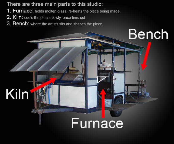
Kiln furnace
A furnace is a solid structure in which a lot of heat energy is generated to produce metal. The different types of furnaces in which different types of metals are produced are:
Blast furnace: This is the structure used for producing pig-iron from Iron Ore.
Bessemer converter: This is the structure used for producing steel from pig iron.
Open hearth furnace: This is the structure used for producing steel from pig-iron.
Electric Arc-furnace: This is the structure used for producing stainless steel.
Cupola furnace: This is the structure used for producing cast iron from pig-iron.
Pudding furnace: This is the structure used for producing wrought-iron.
Reverberating furnace: This is the structure used for producing non-ferrous metals.
LESSON 6
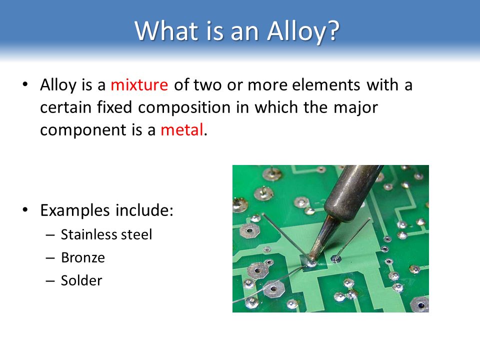
Metal Alloy.
An alloy is a mixture of two or more metals. A non-ferrous alloy is a mixture of two or more non-ferrous metals.
Examples of non-ferrous alloys are Brass, Bronze, Soft Solder, Duralumin, etc.
i. Brass: Brass is a mixture of copper and zinc
Brass= copper + Zinc
ii. Bronze: Bronze is a mixture of copper, Tin and Phosphorus.
Bronze = Copper + Tin + Phosphorus
iii. Soft solder:
Soft solder = Lead + Tin
iv. Duralumin: Duralumin is a mixture of copper, Aluminum and Magnesium
Duralumin = Copper + Aluminum + Magnesium.
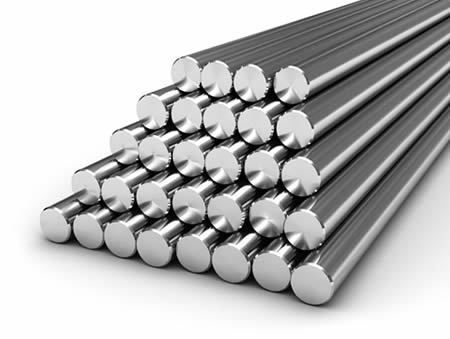
Forms of metals.
1) Bars
2) Wires
3) Sheets
4) Rod
5) Pipes
6) Plates
7) Tubes
8) Channels.
9) Square/ Triangular metals, etc
Production of non-metallic materials
Processing of ceramics:
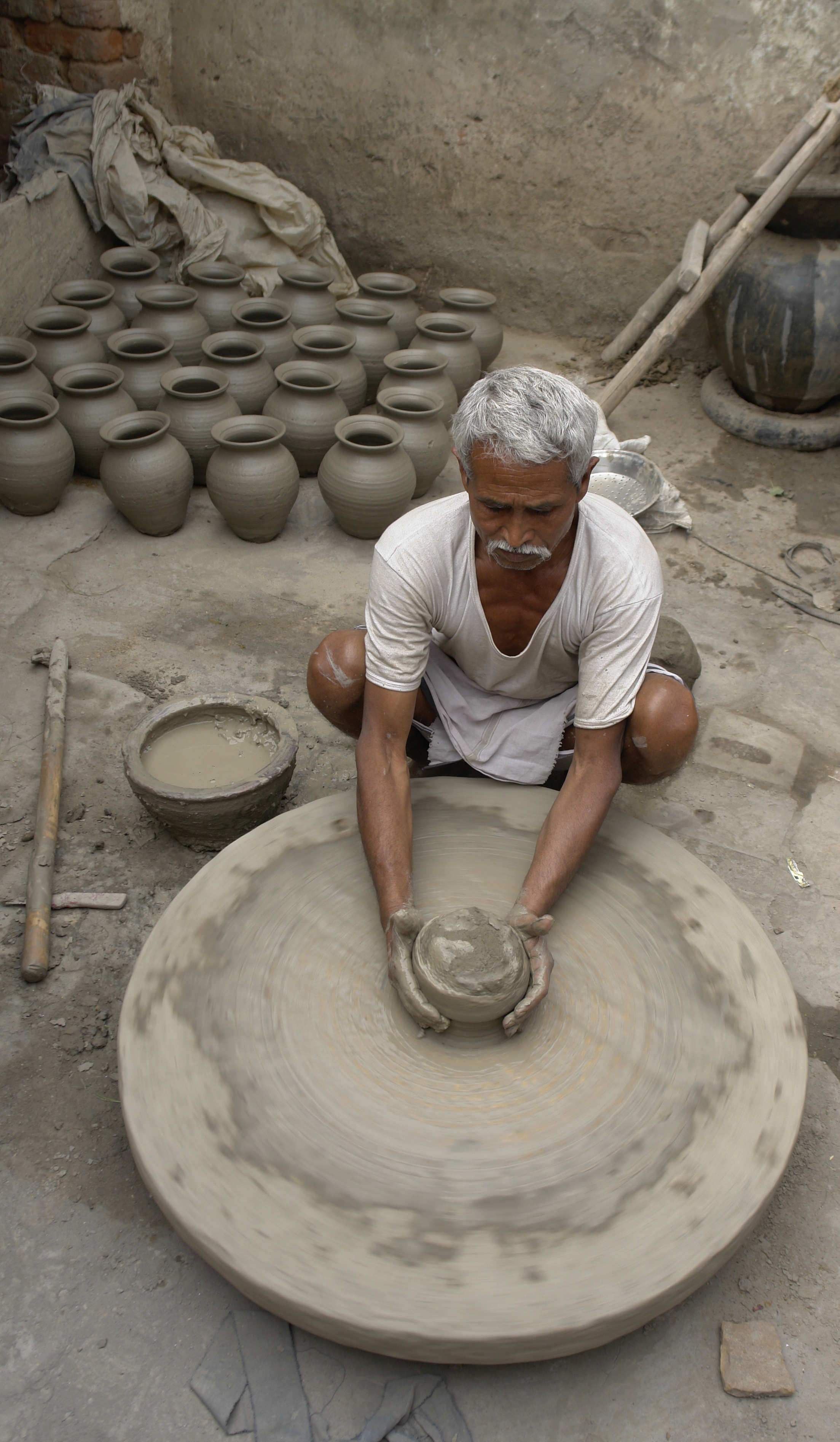
In the processing of ceramic materials, mud and clay are obtained and cleared of all the impurities. Afterwards, the materials are mixed with water thoroughly pounded until a smooth, even mixture is obtained. The next process is shaping of the mixture into the desired objects. The art of making moist clay materials into various objects is called pottery. There are two methods by which ceramic materials can be processed.
i. The pinch method
ii. The potter’s wheel method.
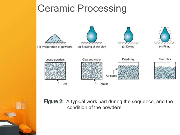
The Pinch method: This is the traditional method of using fingers to carefully mould and shape objects.
The Potter’s wheel method: This is the method with a rotating disc upon which the clay is mould. There are 4 stages involved in the production of ceramics :
i. Molding
ii. Shaping
iii. Decorating.
iv. Firing.
In pottery the following are involved:
a) Mixing
b) Shaping
c) Drying, and
d) Firing.
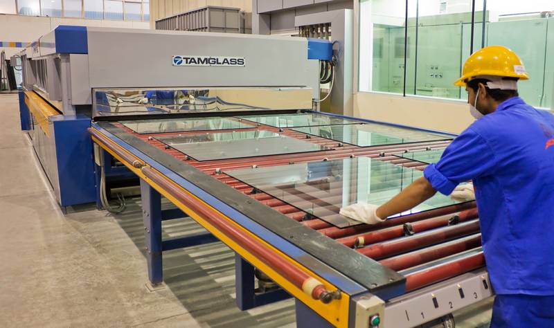
Processing of Glass
The mineral glass belongs to the group of ceramics materials; it is made from inorganic resin made from refining petroleum products. Most glasses in use are the inorganic type. Basically, inorganic glass is produced by melting together various proportions of silica, lime-stone, dolomite by firing them in a furnace. The molten substance is allowed to cool slowly through the process called Annealing.
EVALUATION:
I. List 3 examples of ferrous metals.
II. Mention 3 types of cast iron.
III. List 5 furnaces used in metal production.
IV. State any seven forms of metal.
ASSIGNMENT:
Read New Basic Technology for Junior Secondary Schools Bk 3 by P.O Olawehinmi. Pg 137 on Production of Plastics and Rubber.
TOPIC: PRODUCTION OF METALLIC MATERIALS.
CONTENT :
1. Production of metals: smelting, casting, etc
2. Carbon properties of steels.
3. Metal Alloys
4. Clay, ceramics and glass.
Metallic materials are materials which are referred to as good conductors of heat and electricity. Metals are gotten from Iron ore which is the raw material for metal production. The Iron Ore is dug from the ground along with the impurities (coke, hot air, limestone with Iron Ore).
When the Iron Ore is dug up from the ground, it cannot be used as it contains some impurities, it undergoes certain processes during which these impurities are removed and other substances are added. Since these impurities cannot be removed from iron-ore in its solid state, it is converted into a liquid state by heating. Thus process is known as smelting. The equipment used for this process is called a furnace. After removing these impurities from Iron Ore, the product left is called Pig-Iron.The Pig iron in its ordinary state cannot be used without further processing; this is because pig iron contains saturated iron and carbon. This is weak and can break easily. Hence, it forms the basis of all ferrous metals containing about 45% carbon. In order to render pig iron usable such as cast Iron, steels and wrought Iron, the amount of carbon it contains must be reduced.
1. Cast Iron: This is obtained when pig Iron is put into a cupola furnace. In this furnace, the carbon content is reduced to about 3.5%. The molten Iron is then poured from the furnace into a container, called mould, so as to solidify it. This process of pouring molten iron into a mould to solidify into a described shape is called casting, hence, the name cast iron.
Examples of cast iron
i. Ductile (chilled) cast iron
ii. Malleable cast iron
iii. Grey cast iron
iv. White cast iron.
2. Steel: This is obtained when the carbon content of pig iron is reduced to 1.5 or less. Steels are named according to the carbon content present in them. These steels are called Plain Carbon Steels because they are made up of carbon and iron.
I. Low carbon steel: (mild steel) this contains about 0.3% or less of carbon.
II. Medium carbon steel: This contain between 0.3%- 0.5% of carbon.
III. High carbon steel: This contains between 0.6%- 1.5% of carbon.
Furnaces used are open hearth and Bessemer converter.
3. Wrought Iron: The wrought iron is obtained by removing the carbon content present in the pig iron. It is soft, easily bent and does not break or rust easily. This is almost pure iron with little slag on it. The wrought iron has no carbon content in them. It is almost rust proof. It is malleable and ductile and can be easily forged into the required shape. Wrought Iron is used in the manufacture of chairs, boilers, plates, gears and so forth.
Casting: This is the process of melting and pouring molten metal into the mould where it cools down to solidify.
Smelting: This is the process of extracting metals from its iron-ore to a liquid state by heating. In this process, all impurities are extracted from the Iron- Ore to form pig-iron.
Annealing: This is the process by which metals can be softened.
Alloy steels
All steels are alloys because they contain both iron and carbon. Alloy steel is a combination of plain carbon steel and one or more other elements which are placed in the electric furnace and then heated. This molten mixture is then poured into a mould container and then cooled to solidify. The alloy steels are:
I. High tensile steels: This is also known as Nickel - chrome alloys. These contain iron, carbon, nickel and chromium. They are used for making machine parts which require high tensility and strength.
II. High Speed steels: These contain iron, carbon, tungsten and chromium. Other forms of high speed steels contain cobalt and vanadium. They are used as cutting edges in machines where friction causes excessive heat due to continuous cutting.
III. Stainless steels: These contain Iron, carbon, Nickel or chromium. Nickel and chromium are principally used as coating for the metals so as to make it resistant to corrosion. They are produced in electric furnace.
PROCESSING OF NON-FERROUS METALS:
The non-ferrous metals are the metals which do not have iron content in them, therefore they are not magnetic.
Examples: Copper, Aluminum, Zinc, Gold and Tungsten.
Iron ore is loaded into a furnace and then melted. The desired metal in a molten state is then separated from the mixture. The molten metal is then poured into containers so as to solidify. When this is done on a large scale, a reverberating furnace is used. The furnace is built of clay or other suitable earthen materials and further reinforced with steel on its outer walls.
Kiln furnace
A furnace is a solid structure in which a lot of heat energy is generated to produce metal. The different types of furnaces in which different types of metals are produced are:
Blast furnace: This is the structure used for producing pig-iron from Iron Ore.
Bessemer converter: This is the structure used for producing steel from pig iron.
Open hearth furnace: This is the structure used for producing steel from pig-iron.
Electric Arc-furnace: This is the structure used for producing stainless steel.
Cupola furnace: This is the structure used for producing cast iron from pig-iron.
Pudding furnace: This is the structure used for producing wrought-iron.
Reverberating furnace: This is the structure used for producing non-ferrous metals.
LESSON 6
Metal Alloy.
An alloy is a mixture of two or more metals. A non-ferrous alloy is a mixture of two or more non-ferrous metals.
Examples of non-ferrous alloys are Brass, Bronze, Soft Solder, Duralumin, etc.
i. Brass: Brass is a mixture of copper and zinc
Brass= copper + Zinc
ii. Bronze: Bronze is a mixture of copper, Tin and Phosphorus.
Bronze = Copper + Tin + Phosphorus
iii. Soft solder:
Soft solder = Lead + Tin
iv. Duralumin: Duralumin is a mixture of copper, Aluminum and Magnesium
Duralumin = Copper + Aluminum + Magnesium.
Forms of metals.
1) Bars
2) Wires
3) Sheets
4) Rod
5) Pipes
6) Plates
7) Tubes
8) Channels.
9) Square/ Triangular metals, etc
Production of non-metallic materials
Processing of ceramics:
In the processing of ceramic materials, mud and clay are obtained and cleared of all the impurities. Afterwards, the materials are mixed with water thoroughly pounded until a smooth, even mixture is obtained. The next process is shaping of the mixture into the desired objects. The art of making moist clay materials into various objects is called pottery. There are two methods by which ceramic materials can be processed.
i. The pinch method
ii. The potter’s wheel method.
The Pinch method: This is the traditional method of using fingers to carefully mould and shape objects.
The Potter’s wheel method: This is the method with a rotating disc upon which the clay is mould. There are 4 stages involved in the production of ceramics :
i. Molding
ii. Shaping
iii. Decorating.
iv. Firing.
In pottery the following are involved:
a) Mixing
b) Shaping
c) Drying, and
d) Firing.
Processing of Glass
The mineral glass belongs to the group of ceramics materials; it is made from inorganic resin made from refining petroleum products. Most glasses in use are the inorganic type. Basically, inorganic glass is produced by melting together various proportions of silica, lime-stone, dolomite by firing them in a furnace. The molten substance is allowed to cool slowly through the process called Annealing.
EVALUATION:
I. List 3 examples of ferrous metals.
II. Mention 3 types of cast iron.
III. List 5 furnaces used in metal production.
IV. State any seven forms of metal.
ASSIGNMENT:
Read New Basic Technology for Junior Secondary Schools Bk 3 by P.O Olawehinmi. Pg 137 on Production of Plastics and Rubber.
WEEK 4
LESSON 8
TOPIC: PRODUCTION OF MATERIALS (PLASTICS AND RUBBER)
Content:
1.Methods of producing plastics
2. Methods of producing rubber materials; natural and synthetic Rubber
Methods of producing plastics
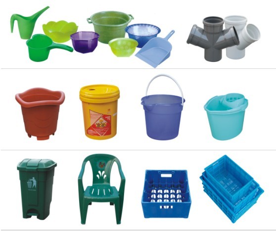
Plastics
Plastics are commonly used both as household items and in big industries. Ordinarily, it is known as a non-metallic lightweight material which comes in various colors. The manufacture of plastics involves the combination of several different components chiefly obtained from petroleum, cellulose, and coal.
Properties of Plastics
I. Plastics are light weight materials, much lighter than wood, ceramics and metals.
II. They have low resistance to heat. They are easily deformed by heat.
III. They do not rust or corrode.
IV. They are good insulators of heat and electricity and that is why they are used as handles of pots, pressing irons, plugs, etc.
Classification of Plastics.
Plastics are of two types: Thermoplastics and Thermoset.
Thermoplastics. These are plastics which become molten again under heat and can therefore be remolded. Examples include most plastic articles used in the homes such as cups, buckets, jerry cans etc.
Thermoset. They are those plastics which cannot be melted into liquid form by heating. Examples are those used in handles of pressing irons, knives and cooking pots. Thermosets are used where high temperature is anticipated.
Manufacturing and Processing of Plastics.
Plastics are derived from organic materials obtained from petroleum. Its production can simply be broken up into the following stages:
i. Obtaining the basic unit called monomer from petroleum.
ii. Polymerization (i.e. joining a large number of molecules) of the monomer to form resins.
iii. Combining the resin with appropriate materials to produce the required plastics.
iv. Molding and shaping of the plastics into different forms.
Methods of producing plastics.
The plastic materials can be molded into any of the required form into any of the required shape when wet through any of the following processes.
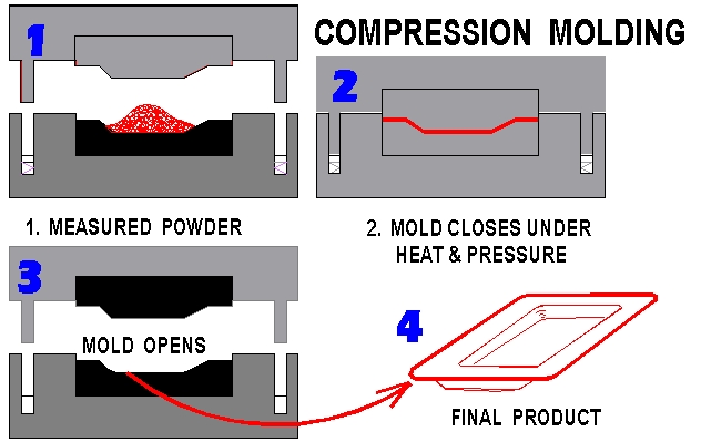
i. The compression molding
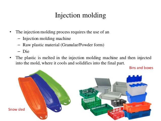
ii. The Injection molding
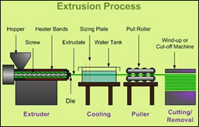
iii. The Extrusion
iv. The Calendaring
v. The Vacuum forming.
The compression molding: This is the method of forming plastic materials in a mould by means of the application of pressure and heat energy. This method is employed in forming thermoset plastics.
The injection molding: This is a method of forming an object by injecting hot molten metals by means of plungers.
The Extrusion: This is the method of heating a plastic material and forcing it through a mould followed by continuous cooling. It is a method used in the manufacture of thermoplastic pipes.
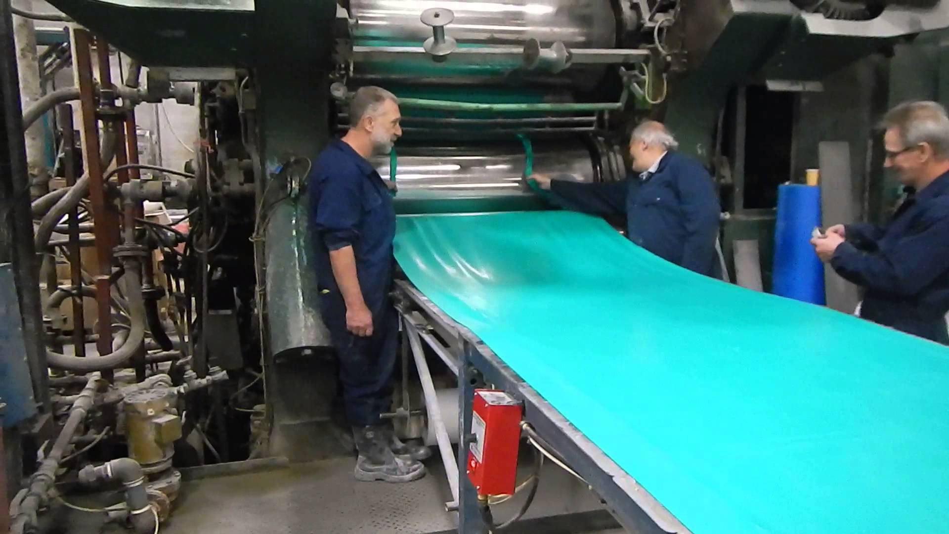
The Calendaring: This is a method for producing thermoplastic sheets in paste form between heated and cooled rollers.
https://youtu.be/r43qiRRVm8I
The Vacuum forming: This is an enclosed method from which air had been completely removed. It is a method for making plastic cups.
LESSON 9
Methods of Processing rubber.
Rubber: is an elastic organic material. Rubber can easily be stretched, and it can return to its original position when the force is released. There are two types of rubber—natural rubber and synthetic rubber.
Properties of Rubber
I. They are elastic.
II. They are water resistant and will float on water. This is why they are used as floats for swimming.
III. They are good electrical insulators. This is why electric wires are covered with rubber.
Manufacture and Processing of Rubber.
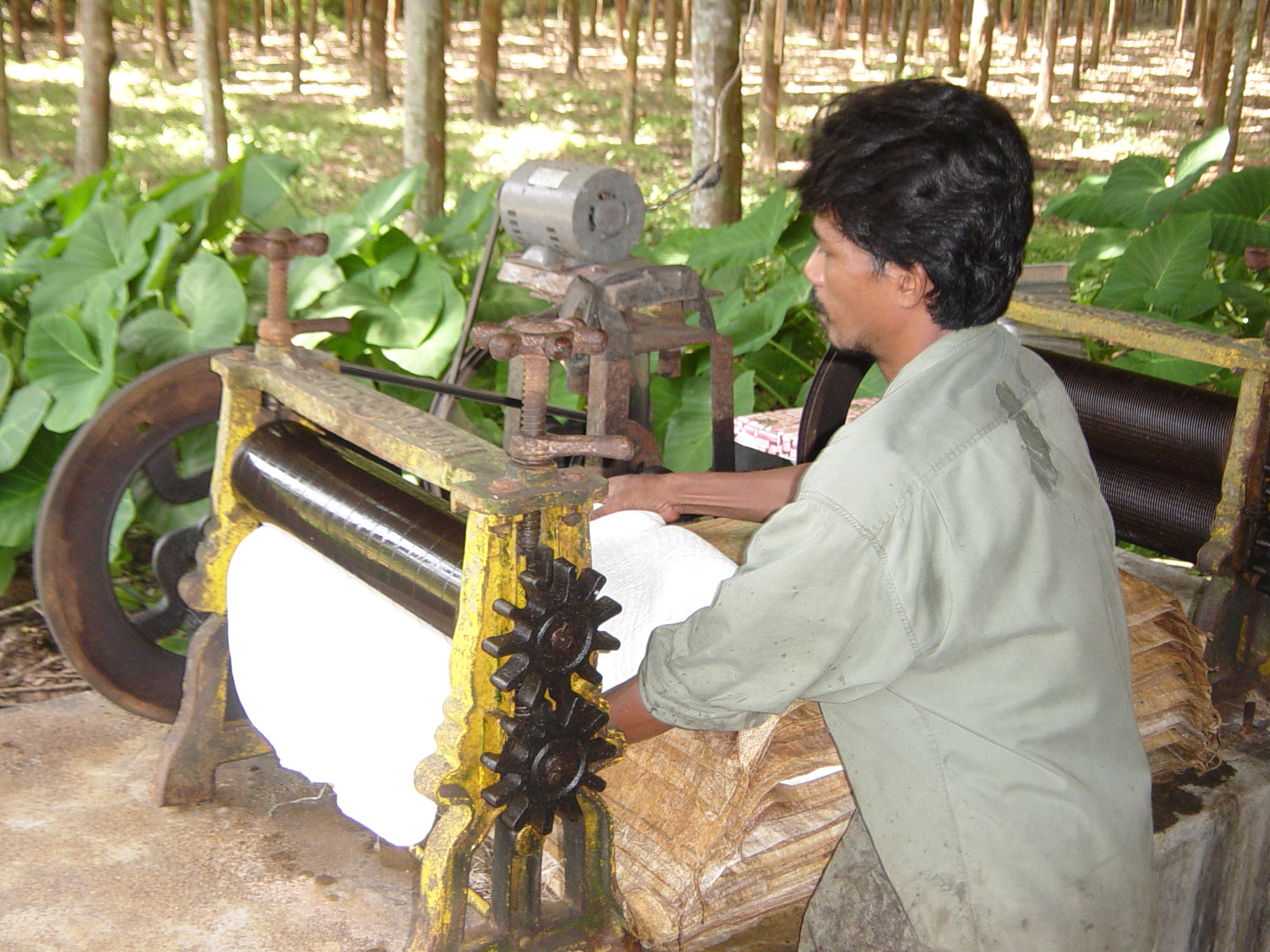
Natural rubber is made from latex ( a milky white liquid) obtained from the rubber tree-‘ Hevea brasiliensis.’ Synthetic rubber on the other hand is obtained from petroleum products. The Natural Latex as found in nature is a white milky sap like fluid. This is used as the raw material for manufacturing natural Rubber. It is extracted from rubber trees.
The synthetic rubber also called neoprene (artificial rubber) is produced by the combination of various chemicals, coal, lime stone, water and sodium chloride by process called polymerization.
Properties of ordinary rubber are not very desirable since they wear out and scratch easily. It needs to be vulcanized to improve its properties. In vulcanization, sulphur is added to the ordinary rubber at high temperatures in the presence of some other compounds. Rubber products are shaped into their form by a number of processes which you will learn about in future.
Carbon black, produced mainly by burning crude oil in special furnaces, is used in tyre compound as reinforcing filler.
Vulcanization of Rubber: The process of improving the quality of rubber by adding sulphur and other chemicals to rubber so as to make the rubber stronger and more elastic.
Uses of Rubber:
• Rubber is a very good shock absorber and is therefore used for making soles of shoes as well as tyres and inner tubes for motor vehicles
• It is also used for making rubber sandals, rainboots, catapults, etc
• For covering electric wires.
The manufacturing of rubber can be processed by any on the following methods:
i. The vacuum forming
ii. The Extrusion
iii. The Calendaring
iv. The compression molding.
EVALUATION:
1) The art of making moist clay materials into various objects is called-----------------
2) The type of rubber produced from petroleum products is known as-----------------
3) The natural rubber is made from a white milky liquid content called-----------------
4) In pottery, clay is mixed with water and pounded to remove---------------------------
Answers: Pottery, Synthetic rubber, Latex, Pebbles.
5) The following are methods of processing plastics EXCEPT
A. Calendaring. B. Extraction C. Injection molding D. Compression molding E. Vacuum Forming.
ASSIGNMENT: Read New Basic Technology for Junior Secondary School, By
P.O Olawehinmi. Pg 139-141. Study the topic ‘Drawing Practice against the next lesson’.
TOPIC: PRODUCTION OF MATERIALS (PLASTICS AND RUBBER)
Content:
1.Methods of producing plastics
2. Methods of producing rubber materials; natural and synthetic Rubber
Methods of producing plastics
Plastics
Plastics are commonly used both as household items and in big industries. Ordinarily, it is known as a non-metallic lightweight material which comes in various colors. The manufacture of plastics involves the combination of several different components chiefly obtained from petroleum, cellulose, and coal.
Properties of Plastics
I. Plastics are light weight materials, much lighter than wood, ceramics and metals.
II. They have low resistance to heat. They are easily deformed by heat.
III. They do not rust or corrode.
IV. They are good insulators of heat and electricity and that is why they are used as handles of pots, pressing irons, plugs, etc.
Classification of Plastics.
Plastics are of two types: Thermoplastics and Thermoset.
Thermoplastics. These are plastics which become molten again under heat and can therefore be remolded. Examples include most plastic articles used in the homes such as cups, buckets, jerry cans etc.
Thermoset. They are those plastics which cannot be melted into liquid form by heating. Examples are those used in handles of pressing irons, knives and cooking pots. Thermosets are used where high temperature is anticipated.
Manufacturing and Processing of Plastics.
Plastics are derived from organic materials obtained from petroleum. Its production can simply be broken up into the following stages:
i. Obtaining the basic unit called monomer from petroleum.
ii. Polymerization (i.e. joining a large number of molecules) of the monomer to form resins.
iii. Combining the resin with appropriate materials to produce the required plastics.
iv. Molding and shaping of the plastics into different forms.
Methods of producing plastics.
The plastic materials can be molded into any of the required form into any of the required shape when wet through any of the following processes.
i. The compression molding
ii. The Injection molding
iii. The Extrusion
iv. The Calendaring
v. The Vacuum forming.
The compression molding: This is the method of forming plastic materials in a mould by means of the application of pressure and heat energy. This method is employed in forming thermoset plastics.
The injection molding: This is a method of forming an object by injecting hot molten metals by means of plungers.
The Extrusion: This is the method of heating a plastic material and forcing it through a mould followed by continuous cooling. It is a method used in the manufacture of thermoplastic pipes.
The Calendaring: This is a method for producing thermoplastic sheets in paste form between heated and cooled rollers.
https://youtu.be/r43qiRRVm8I
The Vacuum forming: This is an enclosed method from which air had been completely removed. It is a method for making plastic cups.
LESSON 9
Methods of Processing rubber.
Rubber: is an elastic organic material. Rubber can easily be stretched, and it can return to its original position when the force is released. There are two types of rubber—natural rubber and synthetic rubber.
Properties of Rubber
I. They are elastic.
II. They are water resistant and will float on water. This is why they are used as floats for swimming.
III. They are good electrical insulators. This is why electric wires are covered with rubber.
Manufacture and Processing of Rubber.
Natural rubber is made from latex ( a milky white liquid) obtained from the rubber tree-‘ Hevea brasiliensis.’ Synthetic rubber on the other hand is obtained from petroleum products. The Natural Latex as found in nature is a white milky sap like fluid. This is used as the raw material for manufacturing natural Rubber. It is extracted from rubber trees.
The synthetic rubber also called neoprene (artificial rubber) is produced by the combination of various chemicals, coal, lime stone, water and sodium chloride by process called polymerization.
Properties of ordinary rubber are not very desirable since they wear out and scratch easily. It needs to be vulcanized to improve its properties. In vulcanization, sulphur is added to the ordinary rubber at high temperatures in the presence of some other compounds. Rubber products are shaped into their form by a number of processes which you will learn about in future.
Carbon black, produced mainly by burning crude oil in special furnaces, is used in tyre compound as reinforcing filler.
Vulcanization of Rubber: The process of improving the quality of rubber by adding sulphur and other chemicals to rubber so as to make the rubber stronger and more elastic.
Uses of Rubber:
• Rubber is a very good shock absorber and is therefore used for making soles of shoes as well as tyres and inner tubes for motor vehicles
• It is also used for making rubber sandals, rainboots, catapults, etc
• For covering electric wires.
The manufacturing of rubber can be processed by any on the following methods:
i. The vacuum forming
ii. The Extrusion
iii. The Calendaring
iv. The compression molding.
EVALUATION:
1) The art of making moist clay materials into various objects is called-----------------
2) The type of rubber produced from petroleum products is known as-----------------
3) The natural rubber is made from a white milky liquid content called-----------------
4) In pottery, clay is mixed with water and pounded to remove---------------------------
Answers: Pottery, Synthetic rubber, Latex, Pebbles.
5) The following are methods of processing plastics EXCEPT
A. Calendaring. B. Extraction C. Injection molding D. Compression molding E. Vacuum Forming.
ASSIGNMENT: Read New Basic Technology for Junior Secondary School, By
P.O Olawehinmi. Pg 139-141. Study the topic ‘Drawing Practice against the next lesson’.
WEEK 5
LESSON 10
TOPIC: DRAWING PRACTICE
SUB-TOPIC:
1. ISOMETRIC DRAWING
2. OBLIQUE DRAWING
The method of drawing solid objects which shows the three dimensions length, width and depth in one view is called pictorial drawing. The pictorial drawing can be divided into three groups:
(a) The isometric drawing
(b) The oblique drawing
(c) The perspective drawing
DEFINITION OF ISOMETRIC DRAWING
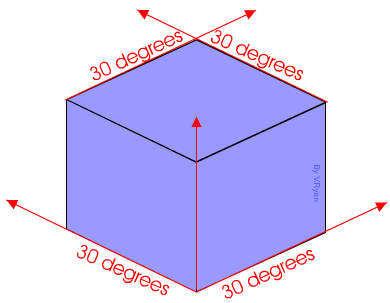
The isometric drawing is the pictorial method of drawing an object in which all the isometric axes are projected to an angle 300 to the horizontal. The isometric drawing shows three axes of an object i.e.
(a) The length
(b) The width
(c) The height
The isometric axes are inclined at an angle 120[sup]0[/sup] to one another. There are (3) three isometric axis one of them is vertical, the other two receding axes are appositely inclined at an angle of 30[sup]0[/sup] to the horizontal. The angle between any two isometric axes is 120[sup]0[/sup].
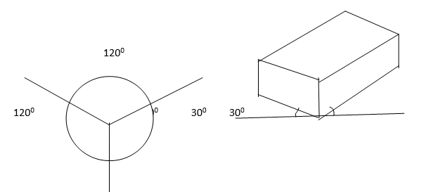
Isometric drawing
The procedures for drawing isometric axes are as follows:
(a) Draw a vertical line AD and locate a point O between A and D. Point O is called the origin
(b) Form point O draw two lines BE and CF to make angle 60 with AO. it will be observed that BE and CF make angle of 30 with horizontal
(c) Any three of the lines OA, OB, OC, OD, OD and OF are called isometric axes provided two of them are not in a straight line.
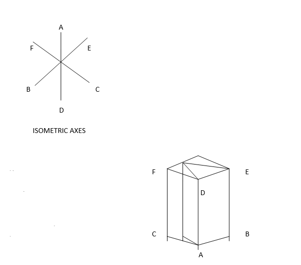
Procedure:
(a) Draw the triangular base ABC of the prism in isometric view
(b) Draw the height AD of the prism.
(c) At point D draw another DEF equal and parallel to triangle ABC
(d) Join BE and CF to complete the prism
OBLIQUE DRAWING
The oblique drawing is the method of drawing the shape of an object in which the projection angles are drawn at the angle 45˚ to the horizontal plane. It recognizes a solid object in three dimensions (length, width and depth), with the front face upright on the plane of the paper.
Two of the three oblique axes are drawn perpendicular to each other, while the third receding axis may be at angle 45˚ to the horizontal.
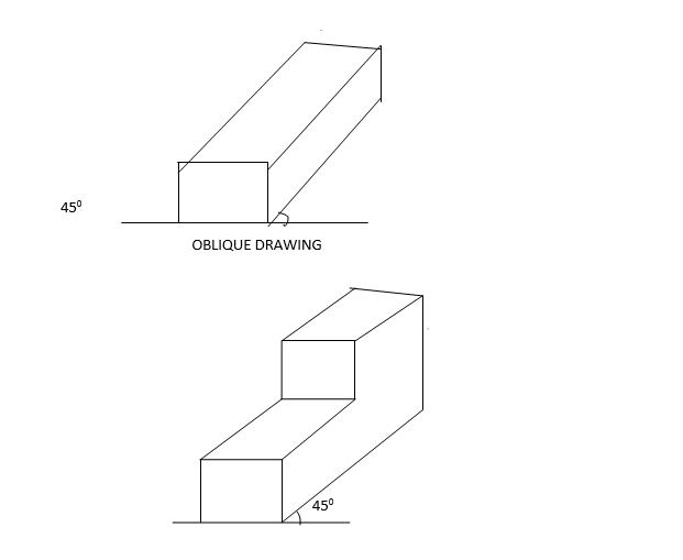

EVALUATION
(i) What is isometric drawing?
(ii) Isometric shows three axes, name them.
(iii) What is oblique drawing
(iv) To what angle do you draw oblique drawing
READING ASSIGNMENT: NEW BASIC TECHNOLOGY FOR JSS (1,2,3) UBE EDITION CHAPTER 7 PAGES 139-140
ASSIGNMENT
(i) What is pictorial drawing?
(ii) What is the difference between isometric drawing and oblique drawing
TOPIC: DRAWING PRACTICE
SUB-TOPIC:
1. ISOMETRIC DRAWING
2. OBLIQUE DRAWING
The method of drawing solid objects which shows the three dimensions length, width and depth in one view is called pictorial drawing. The pictorial drawing can be divided into three groups:
(a) The isometric drawing
(b) The oblique drawing
(c) The perspective drawing
DEFINITION OF ISOMETRIC DRAWING
The isometric drawing is the pictorial method of drawing an object in which all the isometric axes are projected to an angle 300 to the horizontal. The isometric drawing shows three axes of an object i.e.
(a) The length
(b) The width
(c) The height
The isometric axes are inclined at an angle 120[sup]0[/sup] to one another. There are (3) three isometric axis one of them is vertical, the other two receding axes are appositely inclined at an angle of 30[sup]0[/sup] to the horizontal. The angle between any two isometric axes is 120[sup]0[/sup].
Isometric drawing
The procedures for drawing isometric axes are as follows:
(a) Draw a vertical line AD and locate a point O between A and D. Point O is called the origin
(b) Form point O draw two lines BE and CF to make angle 60 with AO. it will be observed that BE and CF make angle of 30 with horizontal
(c) Any three of the lines OA, OB, OC, OD, OD and OF are called isometric axes provided two of them are not in a straight line.
Procedure:
(a) Draw the triangular base ABC of the prism in isometric view
(b) Draw the height AD of the prism.
(c) At point D draw another DEF equal and parallel to triangle ABC
(d) Join BE and CF to complete the prism
OBLIQUE DRAWING
The oblique drawing is the method of drawing the shape of an object in which the projection angles are drawn at the angle 45˚ to the horizontal plane. It recognizes a solid object in three dimensions (length, width and depth), with the front face upright on the plane of the paper.
Two of the three oblique axes are drawn perpendicular to each other, while the third receding axis may be at angle 45˚ to the horizontal.
EVALUATION
(i) What is isometric drawing?
(ii) Isometric shows three axes, name them.
(iii) What is oblique drawing
(iv) To what angle do you draw oblique drawing
READING ASSIGNMENT: NEW BASIC TECHNOLOGY FOR JSS (1,2,3) UBE EDITION CHAPTER 7 PAGES 139-140
ASSIGNMENT
(i) What is pictorial drawing?
(ii) What is the difference between isometric drawing and oblique drawing
WEEK 6
LESSON 11
TOPIC: DRAWING PRACTICE
THE ORTHOGRAPHIC DRAWING
This is the method of drawing an object in which the shape of an object drawn makes a right angle to the plane views. The orthographic drawing means to draw at right angles. It is also known as the working drawing. In the orthographic drawing, two principal planes are used:
(a) Vertical plane
(b) Horizontal plane
When these two planes intersect one another at right angle, it will produce four (4) quadrants (4 angles).
There are three methods of pictorial drawings and pictorial drawing can show a maximum of three views of an object. The three views usually drawn in orthographic drawing are:
(a) Front elevation
(b) Plan
(c) End (side) elevation.
ANGLES OF PROJECTION
The angle of projection depends on which of the four quadrants the object is placed on. The two principal orthographic projections are
(i) The first angle projection (English projection)
(ii) The third angle projection (American projection)
The difference between these two is the method of the arrangement of the views.
THE FIRST ANGLE PROJECTION
The first angle projection is the projection in which the plan is located directly below the front elevation (view). What is seen from the left –hand side is drawn on the right hand side. What is seen from the right-hand side is drawn on the left hand-side. Hence, the plan is located directly below the front elevation (views)
FRONT SIDE
PLAN
FIRST ANGLE PROJECTION
FRONT VIEWS: The front views represent what is seen looking at the front of the objection of arrow (F)
PLAN VIEWS: The plain view represent what is seen when looking from the top of the object in the direction of the arrow (P)
SIDE VIEWS: The side view represent what is seen when looking at the side of the object in the direction of arrow (L)
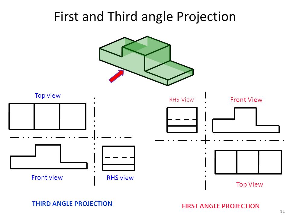
PROPERTIES OF FIRST ANGLE PROJECTION
The following are the properties of the first angle projection.
(i) The plan is always projected below the front view (elevation)
(ii) The right-hand side view is shown on left hand side of the front view
(iii) The left-hand side is shown on the right hand side of the front views.
FIRST ANGLE PROJECTION
EVALUATION
(a) What is orthographic drawing?
(b) State the two angles of orthographic projection.
(c) State properties of first angle projection.
(d) What are the three views in orthographic projection
THE THIRD ANGLE PROJECTION
This is the projection in which the plan is located directly above the front view (elevation). What is seen on the left–hand side is drawn on the left –hand side. What is seen on the right-hand side is drawn on the right side. Hence; the plan is located directly above the front elevation (views).
PLAN
FRONT SIDE
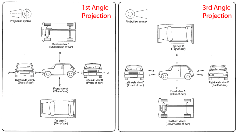
PLAN VIEWS: The plan views represent what is seen when looking from the top of the object in the direction of the arrow (P)
FRONT VIEWS: The front views represent what is seen when looking at the front of the object in the direction of the arrow (F)
SIDE VIEWS: The side views represent what is seen when looking at the side of the object in the direction of the arrow (L)
PROPERTIES OF THIRD ANGLE PROJECTION
The following are the properties of third angle projection.
(i) The plan is always projected above the front views
(ii) The right hand side view is shown on the right hand side view of the elevation (view)
(iii) The left hand side view is shown on the left hand side of the front viewing the direction of the arrow
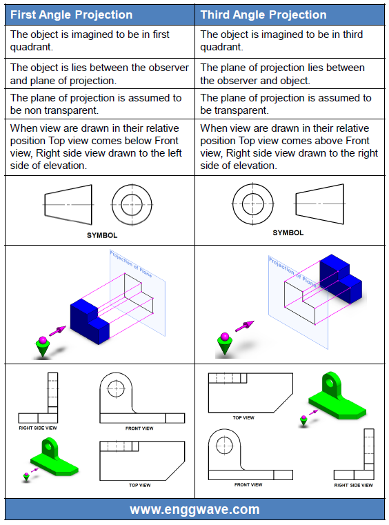
DIMENSION TECHNIQUES
(a) All dimensions on the working drawing must be in the same unit(millimeter).
(b) A working drawing must contain all essential dimensions.
(c) Same dimension should not be repeated in different views to avoid overcrowding of dimension lines.
(d) Projection and dimension lines must be thin; continuous lines and projection lines should extend beyond the dimension lines.
(e) Dimension lines should be at least 10mm away from the outlines, while the projection lines should start at least 1mm away from the outlines.
(f) Projection and dimension lines must not go across other lines in avoidable cases.
(g) Overall dimension should be placed outside smaller dimension.
(h) Arrow head must be sharp and slim. It must touch the projection line. etc
PERSPECTIVE DRAWING
Perspective drawings are the pictorial drawing which shows the three (3) sides of an object at once. In a perspective drawing, all the lines on an object converge to a point called vanishing point (P).
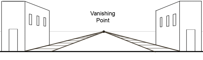
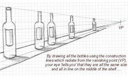
EVALUATION
(a) List five dimension techniques
(b) Explain third angle projection with the aid of line diagram
ASSIGNMENT
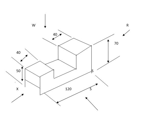
Draw the full size of:
(i) The elevation seen when looking in the direction of arrow (S)
(ii) The plan seen when looking in the direction of arrow (S) in the direction of (W)
(iii) The end elevation seen when looking in the direction of arrow(X)
READING ASSIGNMENT: NEW BASIC TECHNOLOGY FOR JSS (1,2,3) UBE EDITION CHAPTER 5 PAGE 140-143
TOPIC: DRAWING PRACTICE
THE ORTHOGRAPHIC DRAWING
This is the method of drawing an object in which the shape of an object drawn makes a right angle to the plane views. The orthographic drawing means to draw at right angles. It is also known as the working drawing. In the orthographic drawing, two principal planes are used:
(a) Vertical plane
(b) Horizontal plane
When these two planes intersect one another at right angle, it will produce four (4) quadrants (4 angles).
There are three methods of pictorial drawings and pictorial drawing can show a maximum of three views of an object. The three views usually drawn in orthographic drawing are:
(a) Front elevation
(b) Plan
(c) End (side) elevation.
ANGLES OF PROJECTION
The angle of projection depends on which of the four quadrants the object is placed on. The two principal orthographic projections are
(i) The first angle projection (English projection)
(ii) The third angle projection (American projection)
The difference between these two is the method of the arrangement of the views.
THE FIRST ANGLE PROJECTION
The first angle projection is the projection in which the plan is located directly below the front elevation (view). What is seen from the left –hand side is drawn on the right hand side. What is seen from the right-hand side is drawn on the left hand-side. Hence, the plan is located directly below the front elevation (views)
FRONT SIDE
PLAN
FIRST ANGLE PROJECTION
FRONT VIEWS: The front views represent what is seen looking at the front of the objection of arrow (F)
PLAN VIEWS: The plain view represent what is seen when looking from the top of the object in the direction of the arrow (P)
SIDE VIEWS: The side view represent what is seen when looking at the side of the object in the direction of arrow (L)
PROPERTIES OF FIRST ANGLE PROJECTION
The following are the properties of the first angle projection.
(i) The plan is always projected below the front view (elevation)
(ii) The right-hand side view is shown on left hand side of the front view
(iii) The left-hand side is shown on the right hand side of the front views.
FIRST ANGLE PROJECTION
EVALUATION
(a) What is orthographic drawing?
(b) State the two angles of orthographic projection.
(c) State properties of first angle projection.
(d) What are the three views in orthographic projection
THE THIRD ANGLE PROJECTION
This is the projection in which the plan is located directly above the front view (elevation). What is seen on the left–hand side is drawn on the left –hand side. What is seen on the right-hand side is drawn on the right side. Hence; the plan is located directly above the front elevation (views).
PLAN
FRONT SIDE
PLAN VIEWS: The plan views represent what is seen when looking from the top of the object in the direction of the arrow (P)
FRONT VIEWS: The front views represent what is seen when looking at the front of the object in the direction of the arrow (F)
SIDE VIEWS: The side views represent what is seen when looking at the side of the object in the direction of the arrow (L)
PROPERTIES OF THIRD ANGLE PROJECTION
The following are the properties of third angle projection.
(i) The plan is always projected above the front views
(ii) The right hand side view is shown on the right hand side view of the elevation (view)
(iii) The left hand side view is shown on the left hand side of the front viewing the direction of the arrow
DIMENSION TECHNIQUES
(a) All dimensions on the working drawing must be in the same unit(millimeter).
(b) A working drawing must contain all essential dimensions.
(c) Same dimension should not be repeated in different views to avoid overcrowding of dimension lines.
(d) Projection and dimension lines must be thin; continuous lines and projection lines should extend beyond the dimension lines.
(e) Dimension lines should be at least 10mm away from the outlines, while the projection lines should start at least 1mm away from the outlines.
(f) Projection and dimension lines must not go across other lines in avoidable cases.
(g) Overall dimension should be placed outside smaller dimension.
(h) Arrow head must be sharp and slim. It must touch the projection line. etc
PERSPECTIVE DRAWING
Perspective drawings are the pictorial drawing which shows the three (3) sides of an object at once. In a perspective drawing, all the lines on an object converge to a point called vanishing point (P).
EVALUATION
(a) List five dimension techniques
(b) Explain third angle projection with the aid of line diagram
ASSIGNMENT
Draw the full size of:
(i) The elevation seen when looking in the direction of arrow (S)
(ii) The plan seen when looking in the direction of arrow (S) in the direction of (W)
(iii) The end elevation seen when looking in the direction of arrow(X)
READING ASSIGNMENT: NEW BASIC TECHNOLOGY FOR JSS (1,2,3) UBE EDITION CHAPTER 5 PAGE 140-143
WEEK 7
LESSON 12
TOPIC : TOOLS AND MACHINES
SUB-TOPICS:
(a) Woodwork Machines
(b) Simple woodwork Project
Introduction
Before any wood can be used, it has to be cut from the forest and transported to sawmill where further cutting to marketable sizes is carried out. Even after saw milling operation, i.e conversion processes, pieces produced from the sawing of the log will still undergo some kind of sawing to bit and pieces in the attempt to produce a work piece.
In the modern day sawing, through improved technology, various machines are now available mainly to cut wood accurately and much faster.
PORTABLE POWERED HAND TOOLS
HAND DRILL: This is the commonly used. It takes the shape of a gun with the switch set at the trigger point. Hand drills are operated by electric motor to which the chuck’s spindle is connected and driven by it. Various sizes of drill can be connected to the drill’s chuck using the key. The main use of these tools is to bore hole.
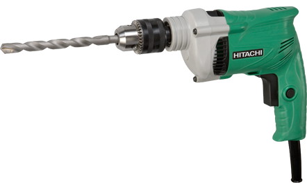
BELT SANDERS: The belt sanders are powered by an a.c motor which rotates one of its rollers. The two rollers are connected by a belt which has been coated with an abrasive. The belts are made of various sizes. Width and length sizes vary from 2 ½-4 (i.e. 6.3 cm-10cm) and 14-24(i.e. 35cm-60cm), respectively.
To operate the belt sander, a belt of right size is fixed by slotting into the machine over the rollers. When the machine is switched on, the belt transmits the motion to the second roller and the same time rotates around the roller at a good speed. It is used for sanding the surface of wood.
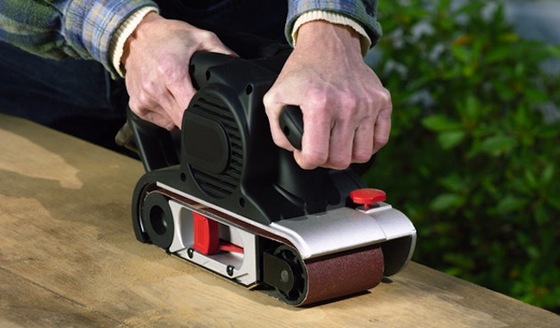
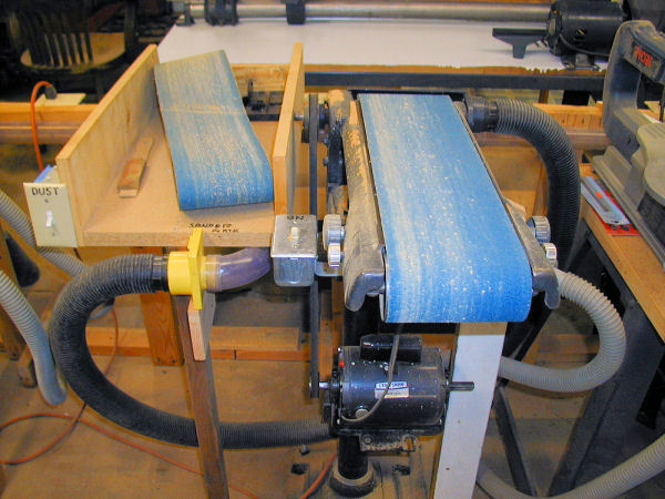
SABER SAW: like fret saw, this power is used to cut complex shapes in wood. The wood in this case may be thicker in size than what fret saw can do. The saw is powered by an electric motor vibrator.
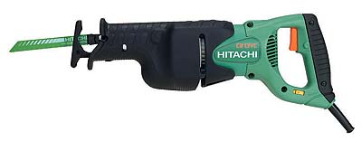
MITRE SAW: It is a power saw with special quick adjustment device that can be used to cut wood at different angles. It has a saw head with tangential deviation of 45˚ with stable and precise bar guide. It contains a pedestal which supports the table and the knife. It is used for cutting mitre. It can also be used for squaring edges of timber.
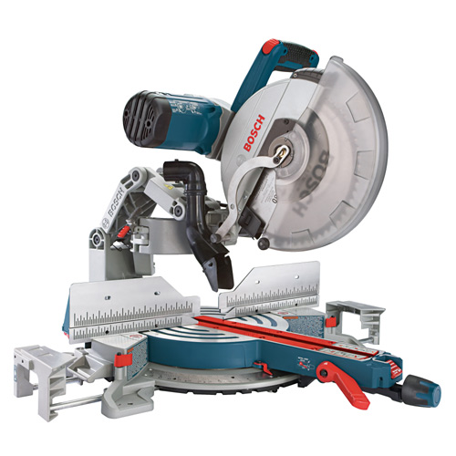
CIRCULAR SAW: This one uses saw of different sizes and teeth. It is powered also by electric motor. The saw can be adjusted to cut to depth and can be used on both timber and laminated board.
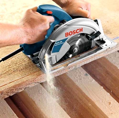
WOOD WORK MACHINE
THE WOOD LATHE: When turning operation is to be carried out, wood lathe machine is used. There are two kinds of turning namely:
(i) Turning between centers and
(ii) Turning on the face plate, both inside and outside.
The basic features of the wood lathe are:
(a) THE HEAD STOCK: This has a treaded spindle on which the face plate and the chucks are mounted.
(b) THE TOOL REST: This feature is a movable item on the bed which is capable of moving forward or backward in any position.
(c) TAIL STOCK: This conical center has a shank that fits into the tail stock.
(d) FACE PLATE: They are accessories of the wood lathe fitted to the head stock’s main spindle for inside or outside turning. The plate usually screwed to the spindle.
USES OF LATHE
The two common uses of lathe machines are:
(1) Cutting chisel and gauge
(2) Scrapping with scrapper, both within centers or on the face plate.
WOOD LATHE
THE CIRCULAR SAWING MACHINE: This derives its name from the circular saw fitted to the machine which may either be used for cross cutting or ripping (i.e cutting along the grain of wood). It has other features apart from the circular saw such as:
(a) An electric motor :This is the source of mechanical energy for powering the saw
(b) Switch control: This is a device for putting the motor on or off.
(c) Fence with locking lever: This is a feature on the machine to guide the wood piece toward the saw.
(d) Control wheel: These controls the depths cut off and are used for tilling the saw blade.
USES
The machine is used for re-sawing timber to accurate sizes for joinery, furniture and other wood work.
[youtube]https://youtu.be/dpA0hYeRVmw[/youtube]
SURFACE PLANNER: This machine is designed for planning work, the most laborious wood work operation. Essential features of the machine are:
(i) An electric motor with switch :This powers the rotating blades
(ii) A fence: to guide the work piece into the running blade.
(iii) A guard: This is a safety device mounted over the cutting blades.
(iv) The cutters: These carry a number of blades.
USES OF THE SURFACE PLANNER
(a) It is used mainly for planning faces and truing edges.
(b) It can also be adopted for rebating, beveling, chamfering, tapering and tenoning.
https://youtu.be/vxyQJCMLCsI
THICKNESSING MACHINE: This machine is used after planning operation on the surface planner. Its essential features are:
(i) Electric motor with switch
(ii) A feed table over which the work piece is placed
(iii) Circular cutter blocks with two or four blades
(iv) Anti-friction roller which are used to control the speed at which wood is fed into the cutters.
USES
The thicknesser is used to produce correct thickness by setting the cutter to the desired size. The wood passes between two cutters.
https://youtu.be/88C8UJOmp9E
BANDSAW MACHINE: It is a machine with a special blade called the band saw. The band saw takes the form of a rubber band with one edge toothed. It is fitted over two pulleys with the lower pulley as driver, so that the saw runs as an endless saw blade. Essential features are:
(i) The saw guide: which gives support to the body of the blade.
(ii) Adjustable fence: for guiding the timber to be cut.
(iii) Band saw compensating and track arrangement: These allow for changes in the strain on the band saw in operation.
USES
It is adopted strictly for cutting straight line cuts and circular or complex shapes and thin wood.
https://youtu.be/HBTQX5dYD_I
DRILL PRESS: Drill press comes in various sizes and design. Its essential features are:
(a) The spindle: This is located and rotated in vertical position.
(b) An electric motor and switch control: To drive the chuck and control motor respectively
(c) A chuck: for holding drill bits
(d) Ground column: for supporting the head.
(e) A titling table: Upon which the work piece is placed can be adjusted with a locking clamp.
(f) Feed lever: This moves the spindle in it enclosure downward.
USES
It is used for drilling operation.
https://youtu.be/dMgKPWY6vXU
EVALUATION
(a) Mention five types of wood machine and briefly explain them
(b) Briefly explain a wood lathe machine.
(c) Distinguish between a thicknesser and surface planer
(d) What are the advantages of wood work machine over wood work hand tools
LESOON 13
WOOD WORK PROJECTS
STAGES IN WOOD WORK
1. DESIGN STAGE: Design is about deciding what size, shape, cost, materials and the use to which, the article produce is put.
2. DRAWING STAGE: This stage is an extension of the first because what is conceived is to be drawn on paper.
3. FABRICATION STAGE: The working drawing is used together with what is called the cutting list.
PROJECT
Making a drill Press Machine
https://youtu.be/9sxcc5F3ALs
MAKING A TEE-SQUARE
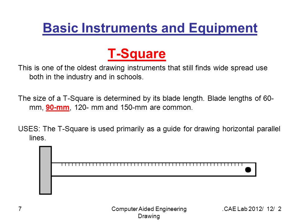
A tee-square is usually made of wood. The working drawing is shown below.
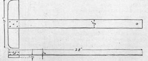
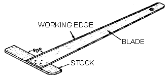
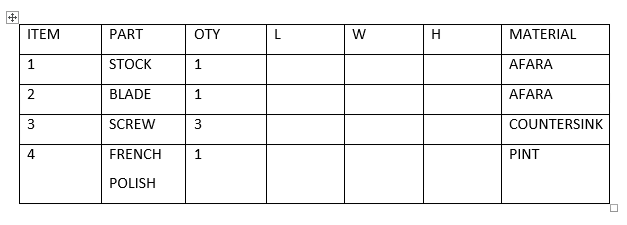
CUTTING LIST
FABRICATION PROCESS
(i) From the available Afara wood board, cut to length given,(in working drawing) the stock and blade.
(ii) Use a plane on the stock and blade, using the same to sharpen the edges.
(iii) Use abrasive to smoothen it.
(iv) Assemble using the screw
(v) Apply French polish.
COMMON WOOD WORK JOINT
BUTT JOINT
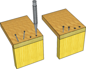
Uses
(a) Window frame construction
(b) Roof construction
(c) For cabinet making
TEE BRIDLE JOINT
Uses
(a) For bracing
(b) It is used at king post and assembling of the beam
Others wood work joint are:
(a) Halving joint
(b) Dovetail joint
(c) Tongue and groove
(d) Mortise and tenon
(e) Housing joint
(f) Dowelled joint.
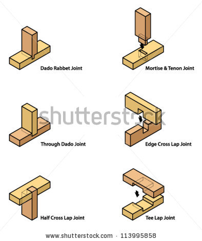
CLASSIFICATION OF JOINTS
(i) Framing joint: Framing joints are used in the construction of frame.
(ii) Widening joints: These involves joining mainly planks, edges to edges to produce a wider board.
(iii) Angle joint: Also called box joint and is used in the formation of angles in wood construction.
USES OF TABLE
(a) Used for reading purpose
(b) Used as a platform for writing
(c) Used for dinning purpose
(d) For ironing of cloth
USES OF BOXES
(i) For storage
(ii) For books-keeping
(iii) Used in importation and exportation of goods
NON WOOD MATERIALS
Non wood materials are material used in wooden constructions that do not possess the characteristics and nature of wood.
Adhesive –This is usually a liquid substance which has power of bonding two or more material together. Different types of adhesives are:
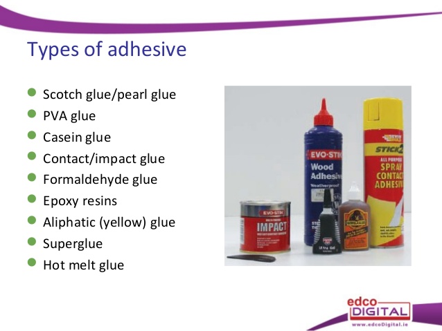
1. PROTEIN ADHESVIES: They include
(a)Vegetable protein glue
(b) Animal protein glue
(c) Blood albumen glue
(d) Casein glue.
2. SYNTHETIC RESIN ADHESIVE: They are adhesive sourced from organic origins which react chemically to weather. There are two types
(a) Thermoplastic types: These are the types that can be soften and removed after bonding by heat e.g. P.V.A.
(b) Thermosetting type: These have a permanent bonding when glued e.g formaldehyde, resorcinol etc.
ABRASIVE
Abrasive are cloth or paper with hard mineral which produces sharp and rough cutting surface that has the ability of wearing way wood and other material by rubbing. Examples are:
(a) Emery
(b) Crushed glass
(c) Aluminum oxide
(d) Crushed quartz
(e) Silicon cabide
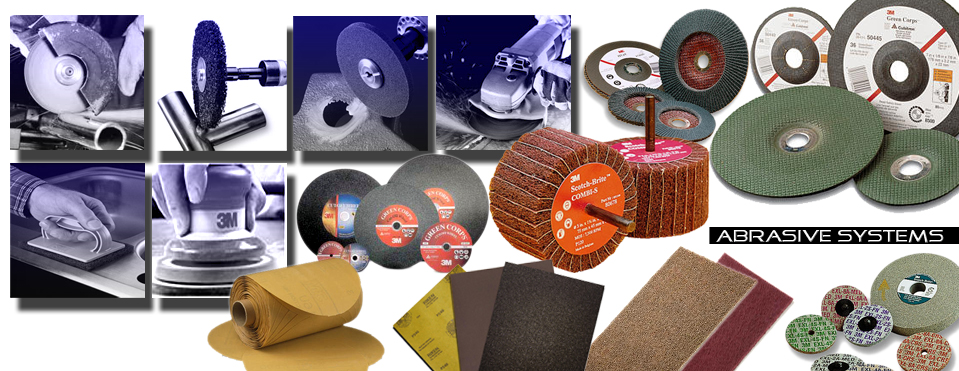
Abrasive can also be classified as
(i) Very fine
(ii) Fine
(iii) Medium
(iv) Coarse
(v) Very coarse
HINGES
They are non-wood material used for installing doors, gates and windows. They are also used in installing covers to boxes, shelves etc. They are three main types of hinges
(a) Tee hinges
(b) Flat hinges
(c) Butt hinges
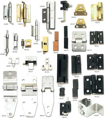
EVALUATION
(a) State the stages involved in wood work project
(b) List three types of hinges
(c) List five example of abrasive
(d) List and explain various types of adhesive
ASSIGNMENT
(a) List and draw five types of wood work joints.
(b) State three uses of tables
(c) State three uses boxes
READING ASSIGNMENT:NEW BASIC TECHNOLOGY FOR JSS (3) SECOND EDITION CHAPTER 8 PAGE 64-79
TOPIC : TOOLS AND MACHINES
SUB-TOPICS:
(a) Woodwork Machines
(b) Simple woodwork Project
Introduction
Before any wood can be used, it has to be cut from the forest and transported to sawmill where further cutting to marketable sizes is carried out. Even after saw milling operation, i.e conversion processes, pieces produced from the sawing of the log will still undergo some kind of sawing to bit and pieces in the attempt to produce a work piece.
In the modern day sawing, through improved technology, various machines are now available mainly to cut wood accurately and much faster.
PORTABLE POWERED HAND TOOLS
HAND DRILL: This is the commonly used. It takes the shape of a gun with the switch set at the trigger point. Hand drills are operated by electric motor to which the chuck’s spindle is connected and driven by it. Various sizes of drill can be connected to the drill’s chuck using the key. The main use of these tools is to bore hole.
BELT SANDERS: The belt sanders are powered by an a.c motor which rotates one of its rollers. The two rollers are connected by a belt which has been coated with an abrasive. The belts are made of various sizes. Width and length sizes vary from 2 ½-4 (i.e. 6.3 cm-10cm) and 14-24(i.e. 35cm-60cm), respectively.
To operate the belt sander, a belt of right size is fixed by slotting into the machine over the rollers. When the machine is switched on, the belt transmits the motion to the second roller and the same time rotates around the roller at a good speed. It is used for sanding the surface of wood.
SABER SAW: like fret saw, this power is used to cut complex shapes in wood. The wood in this case may be thicker in size than what fret saw can do. The saw is powered by an electric motor vibrator.
MITRE SAW: It is a power saw with special quick adjustment device that can be used to cut wood at different angles. It has a saw head with tangential deviation of 45˚ with stable and precise bar guide. It contains a pedestal which supports the table and the knife. It is used for cutting mitre. It can also be used for squaring edges of timber.
CIRCULAR SAW: This one uses saw of different sizes and teeth. It is powered also by electric motor. The saw can be adjusted to cut to depth and can be used on both timber and laminated board.
WOOD WORK MACHINE
THE WOOD LATHE: When turning operation is to be carried out, wood lathe machine is used. There are two kinds of turning namely:
(i) Turning between centers and
(ii) Turning on the face plate, both inside and outside.
The basic features of the wood lathe are:
(a) THE HEAD STOCK: This has a treaded spindle on which the face plate and the chucks are mounted.
(b) THE TOOL REST: This feature is a movable item on the bed which is capable of moving forward or backward in any position.
(c) TAIL STOCK: This conical center has a shank that fits into the tail stock.
(d) FACE PLATE: They are accessories of the wood lathe fitted to the head stock’s main spindle for inside or outside turning. The plate usually screwed to the spindle.
USES OF LATHE
The two common uses of lathe machines are:
(1) Cutting chisel and gauge
(2) Scrapping with scrapper, both within centers or on the face plate.
WOOD LATHE
THE CIRCULAR SAWING MACHINE: This derives its name from the circular saw fitted to the machine which may either be used for cross cutting or ripping (i.e cutting along the grain of wood). It has other features apart from the circular saw such as:
(a) An electric motor :This is the source of mechanical energy for powering the saw
(b) Switch control: This is a device for putting the motor on or off.
(c) Fence with locking lever: This is a feature on the machine to guide the wood piece toward the saw.
(d) Control wheel: These controls the depths cut off and are used for tilling the saw blade.
USES
The machine is used for re-sawing timber to accurate sizes for joinery, furniture and other wood work.
[youtube]https://youtu.be/dpA0hYeRVmw[/youtube]
SURFACE PLANNER: This machine is designed for planning work, the most laborious wood work operation. Essential features of the machine are:
(i) An electric motor with switch :This powers the rotating blades
(ii) A fence: to guide the work piece into the running blade.
(iii) A guard: This is a safety device mounted over the cutting blades.
(iv) The cutters: These carry a number of blades.
USES OF THE SURFACE PLANNER
(a) It is used mainly for planning faces and truing edges.
(b) It can also be adopted for rebating, beveling, chamfering, tapering and tenoning.
https://youtu.be/vxyQJCMLCsI
THICKNESSING MACHINE: This machine is used after planning operation on the surface planner. Its essential features are:
(i) Electric motor with switch
(ii) A feed table over which the work piece is placed
(iii) Circular cutter blocks with two or four blades
(iv) Anti-friction roller which are used to control the speed at which wood is fed into the cutters.
USES
The thicknesser is used to produce correct thickness by setting the cutter to the desired size. The wood passes between two cutters.
https://youtu.be/88C8UJOmp9E
BANDSAW MACHINE: It is a machine with a special blade called the band saw. The band saw takes the form of a rubber band with one edge toothed. It is fitted over two pulleys with the lower pulley as driver, so that the saw runs as an endless saw blade. Essential features are:
(i) The saw guide: which gives support to the body of the blade.
(ii) Adjustable fence: for guiding the timber to be cut.
(iii) Band saw compensating and track arrangement: These allow for changes in the strain on the band saw in operation.
USES
It is adopted strictly for cutting straight line cuts and circular or complex shapes and thin wood.
https://youtu.be/HBTQX5dYD_I
DRILL PRESS: Drill press comes in various sizes and design. Its essential features are:
(a) The spindle: This is located and rotated in vertical position.
(b) An electric motor and switch control: To drive the chuck and control motor respectively
(c) A chuck: for holding drill bits
(d) Ground column: for supporting the head.
(e) A titling table: Upon which the work piece is placed can be adjusted with a locking clamp.
(f) Feed lever: This moves the spindle in it enclosure downward.
USES
It is used for drilling operation.
https://youtu.be/dMgKPWY6vXU
EVALUATION
(a) Mention five types of wood machine and briefly explain them
(b) Briefly explain a wood lathe machine.
(c) Distinguish between a thicknesser and surface planer
(d) What are the advantages of wood work machine over wood work hand tools
LESOON 13
WOOD WORK PROJECTS
STAGES IN WOOD WORK
1. DESIGN STAGE: Design is about deciding what size, shape, cost, materials and the use to which, the article produce is put.
2. DRAWING STAGE: This stage is an extension of the first because what is conceived is to be drawn on paper.
3. FABRICATION STAGE: The working drawing is used together with what is called the cutting list.
PROJECT
Making a drill Press Machine
https://youtu.be/9sxcc5F3ALs
MAKING A TEE-SQUARE
A tee-square is usually made of wood. The working drawing is shown below.
CUTTING LIST
FABRICATION PROCESS
(i) From the available Afara wood board, cut to length given,(in working drawing) the stock and blade.
(ii) Use a plane on the stock and blade, using the same to sharpen the edges.
(iii) Use abrasive to smoothen it.
(iv) Assemble using the screw
(v) Apply French polish.
COMMON WOOD WORK JOINT
BUTT JOINT
Uses
(a) Window frame construction
(b) Roof construction
(c) For cabinet making
TEE BRIDLE JOINT
Uses
(a) For bracing
(b) It is used at king post and assembling of the beam
Others wood work joint are:
(a) Halving joint
(b) Dovetail joint
(c) Tongue and groove
(d) Mortise and tenon
(e) Housing joint
(f) Dowelled joint.
CLASSIFICATION OF JOINTS
(i) Framing joint: Framing joints are used in the construction of frame.
(ii) Widening joints: These involves joining mainly planks, edges to edges to produce a wider board.
(iii) Angle joint: Also called box joint and is used in the formation of angles in wood construction.
USES OF TABLE
(a) Used for reading purpose
(b) Used as a platform for writing
(c) Used for dinning purpose
(d) For ironing of cloth
USES OF BOXES
(i) For storage
(ii) For books-keeping
(iii) Used in importation and exportation of goods
NON WOOD MATERIALS
Non wood materials are material used in wooden constructions that do not possess the characteristics and nature of wood.
Adhesive –This is usually a liquid substance which has power of bonding two or more material together. Different types of adhesives are:
1. PROTEIN ADHESVIES: They include
(a)Vegetable protein glue
(b) Animal protein glue
(c) Blood albumen glue
(d) Casein glue.
2. SYNTHETIC RESIN ADHESIVE: They are adhesive sourced from organic origins which react chemically to weather. There are two types
(a) Thermoplastic types: These are the types that can be soften and removed after bonding by heat e.g. P.V.A.
(b) Thermosetting type: These have a permanent bonding when glued e.g formaldehyde, resorcinol etc.
ABRASIVE
Abrasive are cloth or paper with hard mineral which produces sharp and rough cutting surface that has the ability of wearing way wood and other material by rubbing. Examples are:
(a) Emery
(b) Crushed glass
(c) Aluminum oxide
(d) Crushed quartz
(e) Silicon cabide
Abrasive can also be classified as
(i) Very fine
(ii) Fine
(iii) Medium
(iv) Coarse
(v) Very coarse
HINGES
They are non-wood material used for installing doors, gates and windows. They are also used in installing covers to boxes, shelves etc. They are three main types of hinges
(a) Tee hinges
(b) Flat hinges
(c) Butt hinges
EVALUATION
(a) State the stages involved in wood work project
(b) List three types of hinges
(c) List five example of abrasive
(d) List and explain various types of adhesive
ASSIGNMENT
(a) List and draw five types of wood work joints.
(b) State three uses of tables
(c) State three uses boxes
READING ASSIGNMENT:NEW BASIC TECHNOLOGY FOR JSS (3) SECOND EDITION CHAPTER 8 PAGE 64-79
WEEK 8
LESSON 14
TOPIC :TOOLS AND PROCESSING
SUB-TOPIC
(a) Types of machine and its function
(b) Lathe machine and its function
A machine tool is a machine that cut metals and perform some other operations by manipulation of its parts. The five basic machine tools are:
(i) Lathe
(ii) Shaper and planer
(iii) Milling machine
(iv) Grinding machine
(v) Drill press
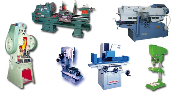
THE MILLING MACHINE
It is of two kinds; the vertical and horizontal milling machine. It can be used to perform what is called up-cut or down-cut. Using either method, the machine is used to:
(a) Cut gear
(b) Cut grooves
(c) Cut splines.
https://youtu.be/RIbdYmmhPDI
DRILL PRESS
Drill press is used for boring or drilling holes in thick metals whose diameter is beyond 25mm.The drill press has its essential features:
(i) An electric motor which drives the drill
(ii) A variable vee -belt that can be changed to select different speed
(iii) A hand lever controlling the up and down movement of drill
(iv) An adjustable tilting table
(v) The chucks
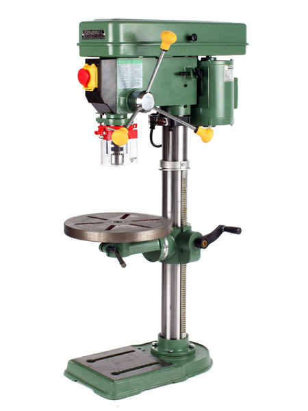
https://youtu.be/6JyIR5nwRho
POWER SAWING MACHINE
The main feature is the power saw blade which is powered by an oscillating mechanism that drives the blade across the rigidly gripped work piece. It is used for cutting metals.

TYPES OF METAL WORK OPERATION
(i) Turning : This involves spurning a work piece against a tool
(ii) Shaping And milling :These refer to pressing, rolling and changing the original shape of a metal
(iii) Drilling : boring of holes in metal
(iv) Grinding: Giving or restoring sharpness of edges or smoothness of face to a metal.
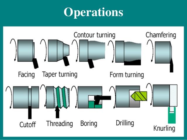
EVALUATION
(a) What is a machine?
(b) List and explain three types of metal work operation.
(c) State the uses of the following metal work machine.
1. Milling machine
2. Power sawing machine
3. Drill press.
LESSON 15
LATHE MACHINE
The most useful and versatile of all machines is the lathe machine. It can perform operation like:
(a) Milling
(b) Turning
(c) Shaping
(d) Cutting.
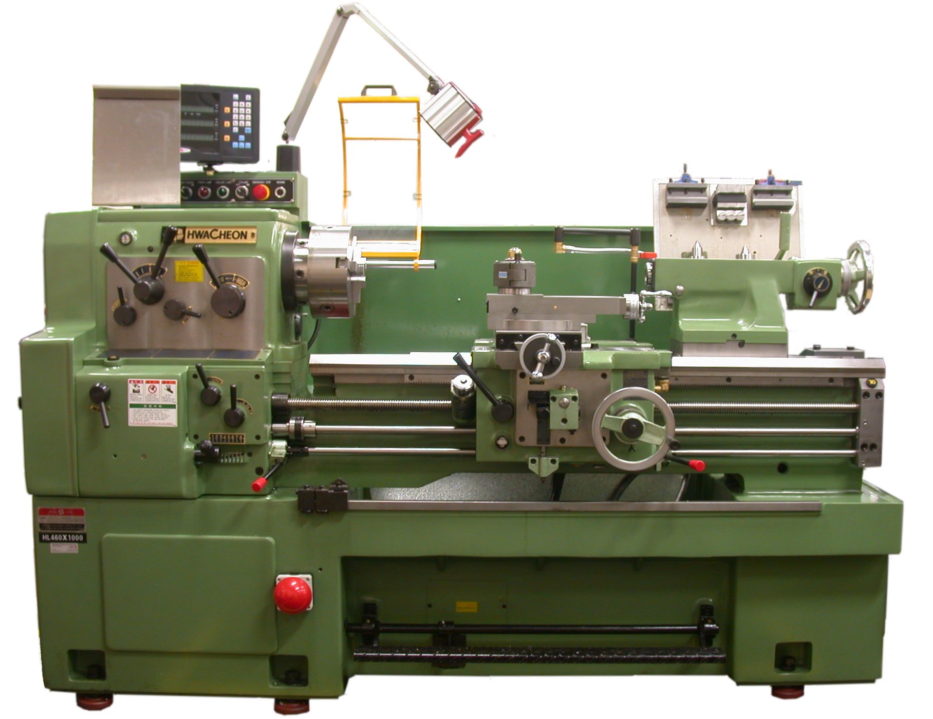
Main feature of lathe
(a) The headstock-This part of the machine is driven by an electric motor. Motion is feed to its spindle through an arrangement of gear mechanism by using control lever, speed.
(b) Work carrier-refer to various fitting on lathe used in holding jobs. They are:
(i) The face plate
(ii) The tool post and
(iii) The carriage
(c) The tail stock-The tailstock is at the end of the lathe; it is designed to be movable so that it can support long pieces of work when turning.
(d) The chuck; this may have 3-jaw or 4—jaw gripping hold. The jaw can be move both inward and outward and are locked by a key
(e) Driving plate; A slander work piece is always supported between two centers before worked on using driving plate.
(f) Faceplate; when the work piece has an awkward or irregular shape and has to be turned for it to have a flat surface or at right angles to a flat surface, the faceplate is used.
OPERATIONS ON THE LATHE MACHINE
There are five major operations that could be carried out using the lathe machine.
https://youtu.be/r7tvsqUIf2U
(i) Facing –The generation of plane surface is called facing. The cutting edge is placed at right angle to the axis of the work piece. The length of the work is reduced by moving the cutting tool across the end of the work.
(ii) Plain turning- This method of turning produces cylindrical surfaces. Also called parallel turning. The diameter uniformly reduced along the axis.
(iii) Stepped turning- Similar to plain turning but different cutting tool is adjusted to produce plain, surface of different diameter at interval on the same work piece
(iv) Taper turning-The generate taper (i.e. reducing diameter along axial length) on a work piece.
(v) Drilling- Drilling can also be done on the lathe machine by fitting the chuck of the drill to the tail stock and holding the work piece to be drilled on the chuck of the headstock, the hole is bored horizontally.
https://youtu.be/9qt5ui3P9QA
Evaluation
(a) List five parts of metal work lathe machine
(b) Explain the following terms
1. Taper turning
2. Drilling
3. Stepped turning
ASSIGNMENT
(a) Explain six (6) parts of a metal work lathe machine.
(b) List four operations a metal work lathe machine can perform.
READING ASSIGNMENT:NEW BASIC TECHNOLOGY FOR JSS (3) SECOND EDITION CHAPTER 9 PAGE 80-89
TOPIC :TOOLS AND PROCESSING
SUB-TOPIC
(a) Types of machine and its function
(b) Lathe machine and its function
A machine tool is a machine that cut metals and perform some other operations by manipulation of its parts. The five basic machine tools are:
(i) Lathe
(ii) Shaper and planer
(iii) Milling machine
(iv) Grinding machine
(v) Drill press
THE MILLING MACHINE
It is of two kinds; the vertical and horizontal milling machine. It can be used to perform what is called up-cut or down-cut. Using either method, the machine is used to:
(a) Cut gear
(b) Cut grooves
(c) Cut splines.
https://youtu.be/RIbdYmmhPDI
DRILL PRESS
Drill press is used for boring or drilling holes in thick metals whose diameter is beyond 25mm.The drill press has its essential features:
(i) An electric motor which drives the drill
(ii) A variable vee -belt that can be changed to select different speed
(iii) A hand lever controlling the up and down movement of drill
(iv) An adjustable tilting table
(v) The chucks
https://youtu.be/6JyIR5nwRho
POWER SAWING MACHINE
The main feature is the power saw blade which is powered by an oscillating mechanism that drives the blade across the rigidly gripped work piece. It is used for cutting metals.
TYPES OF METAL WORK OPERATION
(i) Turning : This involves spurning a work piece against a tool
(ii) Shaping And milling :These refer to pressing, rolling and changing the original shape of a metal
(iii) Drilling : boring of holes in metal
(iv) Grinding: Giving or restoring sharpness of edges or smoothness of face to a metal.
EVALUATION
(a) What is a machine?
(b) List and explain three types of metal work operation.
(c) State the uses of the following metal work machine.
1. Milling machine
2. Power sawing machine
3. Drill press.
LESSON 15
LATHE MACHINE
The most useful and versatile of all machines is the lathe machine. It can perform operation like:
(a) Milling
(b) Turning
(c) Shaping
(d) Cutting.
Main feature of lathe
(a) The headstock-This part of the machine is driven by an electric motor. Motion is feed to its spindle through an arrangement of gear mechanism by using control lever, speed.
(b) Work carrier-refer to various fitting on lathe used in holding jobs. They are:
(i) The face plate
(ii) The tool post and
(iii) The carriage
(c) The tail stock-The tailstock is at the end of the lathe; it is designed to be movable so that it can support long pieces of work when turning.
(d) The chuck; this may have 3-jaw or 4—jaw gripping hold. The jaw can be move both inward and outward and are locked by a key
(e) Driving plate; A slander work piece is always supported between two centers before worked on using driving plate.
(f) Faceplate; when the work piece has an awkward or irregular shape and has to be turned for it to have a flat surface or at right angles to a flat surface, the faceplate is used.
OPERATIONS ON THE LATHE MACHINE
There are five major operations that could be carried out using the lathe machine.
https://youtu.be/r7tvsqUIf2U
(i) Facing –The generation of plane surface is called facing. The cutting edge is placed at right angle to the axis of the work piece. The length of the work is reduced by moving the cutting tool across the end of the work.
(ii) Plain turning- This method of turning produces cylindrical surfaces. Also called parallel turning. The diameter uniformly reduced along the axis.
(iii) Stepped turning- Similar to plain turning but different cutting tool is adjusted to produce plain, surface of different diameter at interval on the same work piece
(iv) Taper turning-The generate taper (i.e. reducing diameter along axial length) on a work piece.
(v) Drilling- Drilling can also be done on the lathe machine by fitting the chuck of the drill to the tail stock and holding the work piece to be drilled on the chuck of the headstock, the hole is bored horizontally.
https://youtu.be/9qt5ui3P9QA
Evaluation
(a) List five parts of metal work lathe machine
(b) Explain the following terms
1. Taper turning
2. Drilling
3. Stepped turning
ASSIGNMENT
(a) Explain six (6) parts of a metal work lathe machine.
(b) List four operations a metal work lathe machine can perform.
READING ASSIGNMENT:NEW BASIC TECHNOLOGY FOR JSS (3) SECOND EDITION CHAPTER 9 PAGE 80-89
WEEK 9
LESSON 16
TOPIC: TOOLS AND PROCESSING
SUB-TOPIC (a) Simple metal work project
(b) Soldering and brazing
Sheet metal work and forging are two aspect of metal work leading to the production of various article. The work is to be carried out in various stages. First stage is shape development.
Shape development involves drawing out a pattern from which the article is produced. To mark out the required lengths, widths, angles and curves on metals certain tools are needed e.g. steel rule, caliper, protractor center punch etc.
The outline of the article is transferred by measurement on the flat metal sheet using the marking out tool; e.g. scriber, try square odd leg caliper etc.
TOOLS AND CUTTING
Different kinds of cutting tools can be used to cut out different shapes. These include:
(a) Chisel
(b) Set snips
(c) Bench shear
(d) Hacksaw
Each tool is selected on the basis of two factors the thickness of the metal to be cut and the shape to be cut.
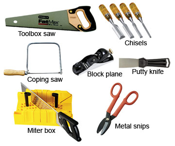
FILES AND FILLING
Filling operation on metal is the process of removing excess metal on a metal. There are different types of files used in metal work. When using files, it is necessary to know how to safely handle them.
(i) Never use a file without handle
(ii) Never use a file on a welded joint
(iii) Never use a file on steel, but slightly on the bench vice before filling
(iv) Clean always the files.
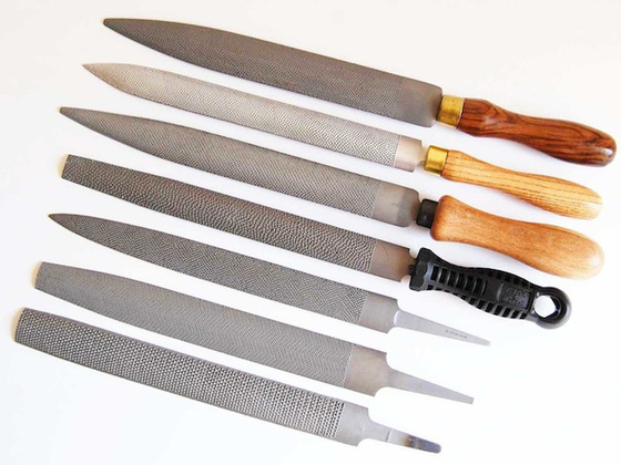
TYPES OF FILES
(a) Flat file
(b) Hand file
(c) Warding file
(d) Square file
(e) Triangular file
(f) Round file etc
EVALUATION
(a) List five types of file.
(b) What is filling
(c) List three safety precaution to be observed when using file
LESSON 17
DRILL AND DRILLING
Hole in metal are usually made in different ways either by drilling, punching and boring. The most common method is the use of drill/drilling bit and drilling machine. Drills are usually fitted through chucks key to the chucks of the machines. Drilling machines to which these drill are attached could be either of:
(i) Manual hand-drilling machine
(ii) Portable electrical hand-drilling machine
(iii) Sensitive drilling machine
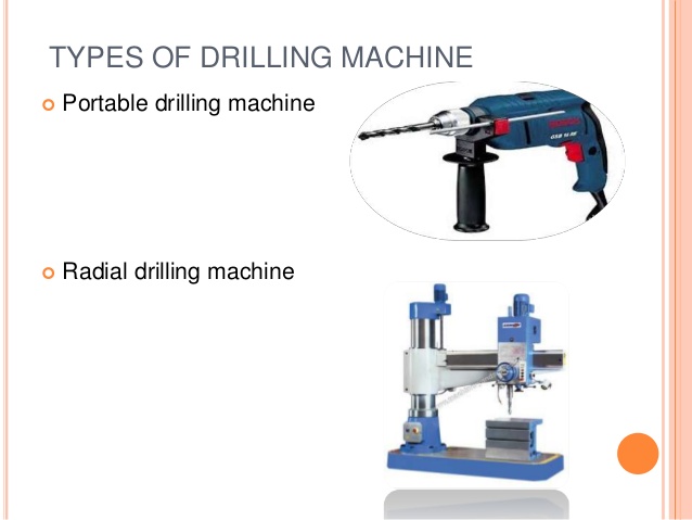
Drill used in metal work includes:
(a) Counter sink
(b) Flat
(c) Straight fluted
(d) Twist
(e) Combination.
https://youtu.be/2O-kwi-KqvE
BENDING AND FOLDING
Bending operation in metal work applies to flat sheet of metal and thick sizes. Bending is the making the sheet of metal or thick sizes metal to have curves and angles required to make certain metal products. Folding and wiring apply mainly to flat sheets. It is the act of preparing and making edges of products to have round smooth finish, thus protecting the product from tear and likewise the user of the product. Some of the tools used in bending and folding include:
(a) Bench vice
(b) Hatchet stakes
(c) Round bars
(d) Anvil
(e) Raising mallet
(f) Grover
(g) Boxwood bossing
(h) Folding bars
(i) Funnel stake creasing iron
(j) Round bottom stake
(k) Bick iron etc.
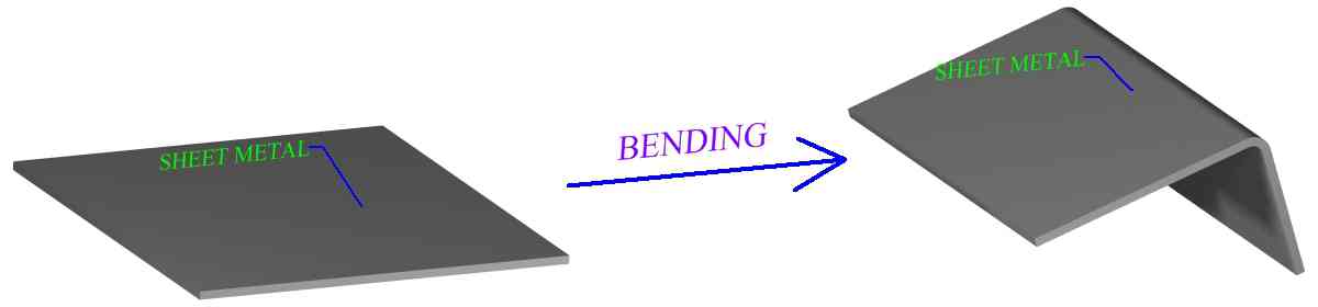
SOLDERING AND BRAZING
DEFINITION OF SOLDERING: Soldering is the process of joining two or more metals together by the use of heat. There are two types of soldering
1. HARD SOLDERING: It is a form of soldering which requires a high temperature. Hard soldering may involve brazing and silver soldering. It is used for hard/tough materials and where great strength is needed.
2. SOFT SOLDERING: It is a form of soldering which requires a low temperature. It uses soft solder, an alloy of lead, tin, antimony and bismuth. It is used for light material that does not need excess heat and also where great strength is not necessary.
FLUX- Flux is needed in both hard and soft soldering. The reasons for this include:
(a) To keep metal clean when heating
(b) To break down surface tension of the solder and allow easy flow of flux.
Tools required for soldering
(i) Gas heater
(ii) Straight bit
(iii) Hatchet bit.
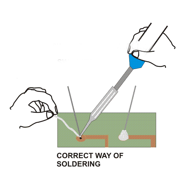
https://youtu.be/H3-TfdZVBCc
BRAZING- It is a process of joining two or more metals together using a solder called spelter. An alloy of copper, zinc strip and wire where strength and high level of heat is required. The following are required for the brazing process:
(a) Heat source
(b) Filler metal
(c) Flux
There are three types of brazing
(i) Copper brazing
(ii) Silver brazing
(iii) Aluminum brazing
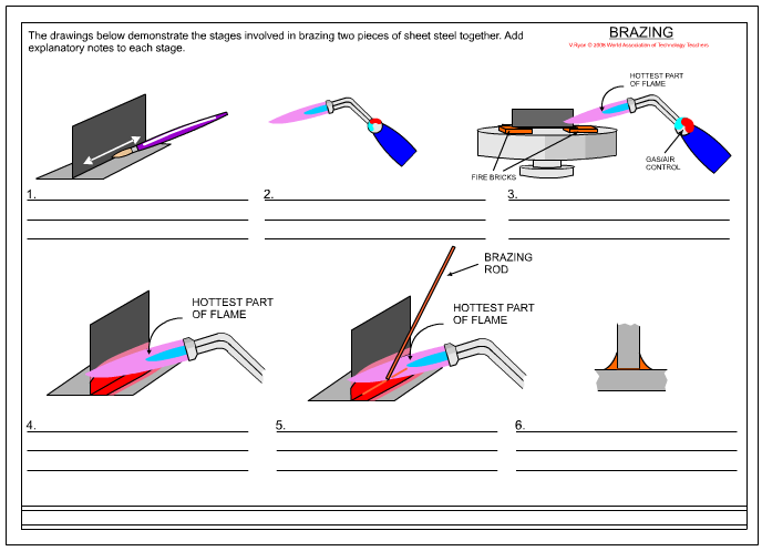
EVALUATION
(a) Draw a bit and label it
(b) Mention three methods of joining metal
(c) List three types of brazing
ASSIGNMENT
(a) What is brazing
(b) State the purpose of flux in soldering
(c) List and explain the two types of soldering
READING ASSIGNMENT: NEW BASIC TECHNOLOGY FOR JSS (1,2,3) UBE EDITION CHAPTER 7 PAGE 152-159
TOPIC: TOOLS AND PROCESSING
SUB-TOPIC (a) Simple metal work project
(b) Soldering and brazing
Sheet metal work and forging are two aspect of metal work leading to the production of various article. The work is to be carried out in various stages. First stage is shape development.
Shape development involves drawing out a pattern from which the article is produced. To mark out the required lengths, widths, angles and curves on metals certain tools are needed e.g. steel rule, caliper, protractor center punch etc.
The outline of the article is transferred by measurement on the flat metal sheet using the marking out tool; e.g. scriber, try square odd leg caliper etc.
TOOLS AND CUTTING
Different kinds of cutting tools can be used to cut out different shapes. These include:
(a) Chisel
(b) Set snips
(c) Bench shear
(d) Hacksaw
Each tool is selected on the basis of two factors the thickness of the metal to be cut and the shape to be cut.
FILES AND FILLING
Filling operation on metal is the process of removing excess metal on a metal. There are different types of files used in metal work. When using files, it is necessary to know how to safely handle them.
(i) Never use a file without handle
(ii) Never use a file on a welded joint
(iii) Never use a file on steel, but slightly on the bench vice before filling
(iv) Clean always the files.
TYPES OF FILES
(a) Flat file
(b) Hand file
(c) Warding file
(d) Square file
(e) Triangular file
(f) Round file etc
EVALUATION
(a) List five types of file.
(b) What is filling
(c) List three safety precaution to be observed when using file
LESSON 17
DRILL AND DRILLING
Hole in metal are usually made in different ways either by drilling, punching and boring. The most common method is the use of drill/drilling bit and drilling machine. Drills are usually fitted through chucks key to the chucks of the machines. Drilling machines to which these drill are attached could be either of:
(i) Manual hand-drilling machine
(ii) Portable electrical hand-drilling machine
(iii) Sensitive drilling machine
Drill used in metal work includes:
(a) Counter sink
(b) Flat
(c) Straight fluted
(d) Twist
(e) Combination.
https://youtu.be/2O-kwi-KqvE
BENDING AND FOLDING
Bending operation in metal work applies to flat sheet of metal and thick sizes. Bending is the making the sheet of metal or thick sizes metal to have curves and angles required to make certain metal products. Folding and wiring apply mainly to flat sheets. It is the act of preparing and making edges of products to have round smooth finish, thus protecting the product from tear and likewise the user of the product. Some of the tools used in bending and folding include:
(a) Bench vice
(b) Hatchet stakes
(c) Round bars
(d) Anvil
(e) Raising mallet
(f) Grover
(g) Boxwood bossing
(h) Folding bars
(i) Funnel stake creasing iron
(j) Round bottom stake
(k) Bick iron etc.
SOLDERING AND BRAZING
DEFINITION OF SOLDERING: Soldering is the process of joining two or more metals together by the use of heat. There are two types of soldering
1. HARD SOLDERING: It is a form of soldering which requires a high temperature. Hard soldering may involve brazing and silver soldering. It is used for hard/tough materials and where great strength is needed.
2. SOFT SOLDERING: It is a form of soldering which requires a low temperature. It uses soft solder, an alloy of lead, tin, antimony and bismuth. It is used for light material that does not need excess heat and also where great strength is not necessary.
FLUX- Flux is needed in both hard and soft soldering. The reasons for this include:
(a) To keep metal clean when heating
(b) To break down surface tension of the solder and allow easy flow of flux.
Tools required for soldering
(i) Gas heater
(ii) Straight bit
(iii) Hatchet bit.
https://youtu.be/H3-TfdZVBCc
BRAZING- It is a process of joining two or more metals together using a solder called spelter. An alloy of copper, zinc strip and wire where strength and high level of heat is required. The following are required for the brazing process:
(a) Heat source
(b) Filler metal
(c) Flux
There are three types of brazing
(i) Copper brazing
(ii) Silver brazing
(iii) Aluminum brazing
EVALUATION
(a) Draw a bit and label it
(b) Mention three methods of joining metal
(c) List three types of brazing
ASSIGNMENT
(a) What is brazing
(b) State the purpose of flux in soldering
(c) List and explain the two types of soldering
READING ASSIGNMENT: NEW BASIC TECHNOLOGY FOR JSS (1,2,3) UBE EDITION CHAPTER 7 PAGE 152-159